Surgical pneumatic motor for use with MRI

a pneumatic motor and surgical technology, applied in the field of pneumatic motors, can solve the problems of not meeting the needs of surgeons and using any medical instrument, and achieve the effect of improving the surgical motor

Active Publication Date: 2009-05-05
ANSPACH EFFORT
View PDF5 Cites 2 Cited by
  • Summary
  • Abstract
  • Description
  • Claims
  • Application Information

AI Technical Summary

Benefits of technology

[0024]Another object of this invention is to provide an improved surgical motor characterized as having spindle bearings with alternating metal and plastic needles, zero velocity axial thrust support for minimizing wear and lower heat, laminated seal for lower velocity and lower heat, increased vane working surface for augmenting the power of the motor, angled slots formed on the spindle to enhance power of the motor and minimizes wear by discretely, spindle end thrust bearings to prevent metal-to-metal on outward exerted axial thrust, exhaust holes formed on the cylinder discharging compressed air are judiciously located to minimize wear on the edge of the vane by distributing contact area evenly and to reduce noise of the motor, cylindrical holes for the input air to the vane motor so as to increase air volume, cylinder crescent seal to increase the effectiveness of the spindle-to-cylinder gap seal and minimize lubrication requirements, stainless steel housing and isolation peek sleeve, increased power cycle by increasing the circumferential spacing between the vane motor's inlet and outlet ports, noise reduction by crisscrossing outlet air flow, slots in the cylinder formed adjacent to the inlet holes for directing air cool over the cylinder before entering the vane motor.

Problems solved by technology

As one skilled in the medical field appreciates, it is unacceptable to use any medical instrument that would interfere with the magnetic field of a magnetic resonance imaging machine (MRI).
However, this motor for some medical procedures does not meet the needs of the surgeons because it lacked the necessary power which gave rise to the Micro Max Plus motor, which, again, has more power than the Micro Max but, yet, less power than the Black Max.

Method used


Image

  • Surgical pneumatic motor for use with MRI
  • Surgical pneumatic motor for use with MRI
  • Surgical pneumatic motor for use with MRI

Examples


Embodiment Construction

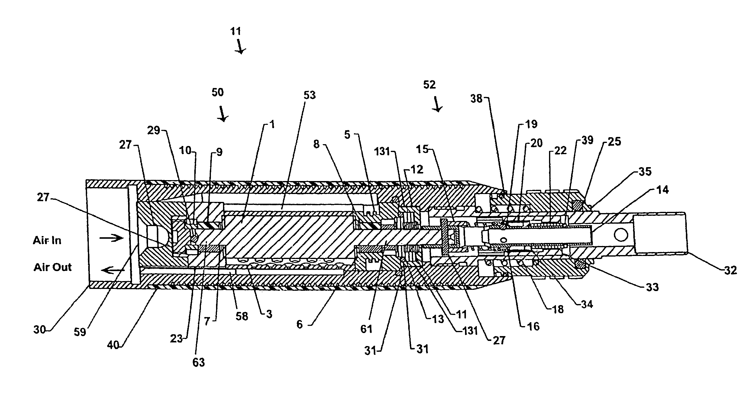
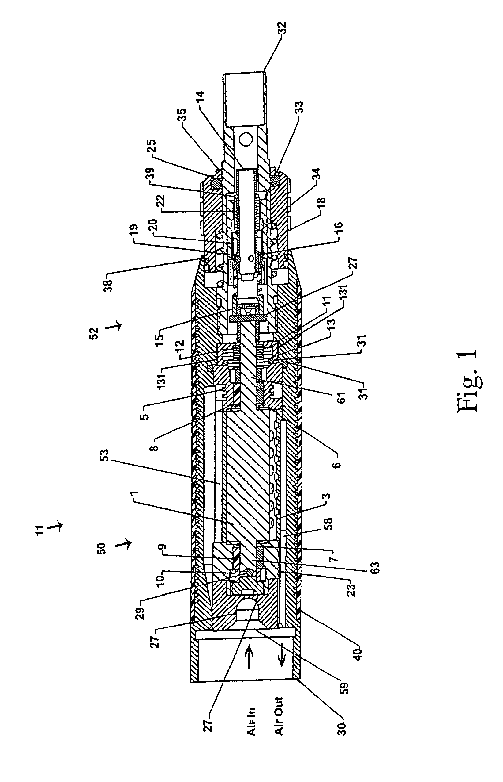
[0045]While in its preferred embodiment this invention is usable with an MRI machine without jeopardizing the magnetism associated with this machine, it will be appreciated by one skilled in this art that this invention can be utilized in other environment and where it is not intended to be used for MRI applications, it could be fabricated from different materials which typically would be less expensive or have other advantages.

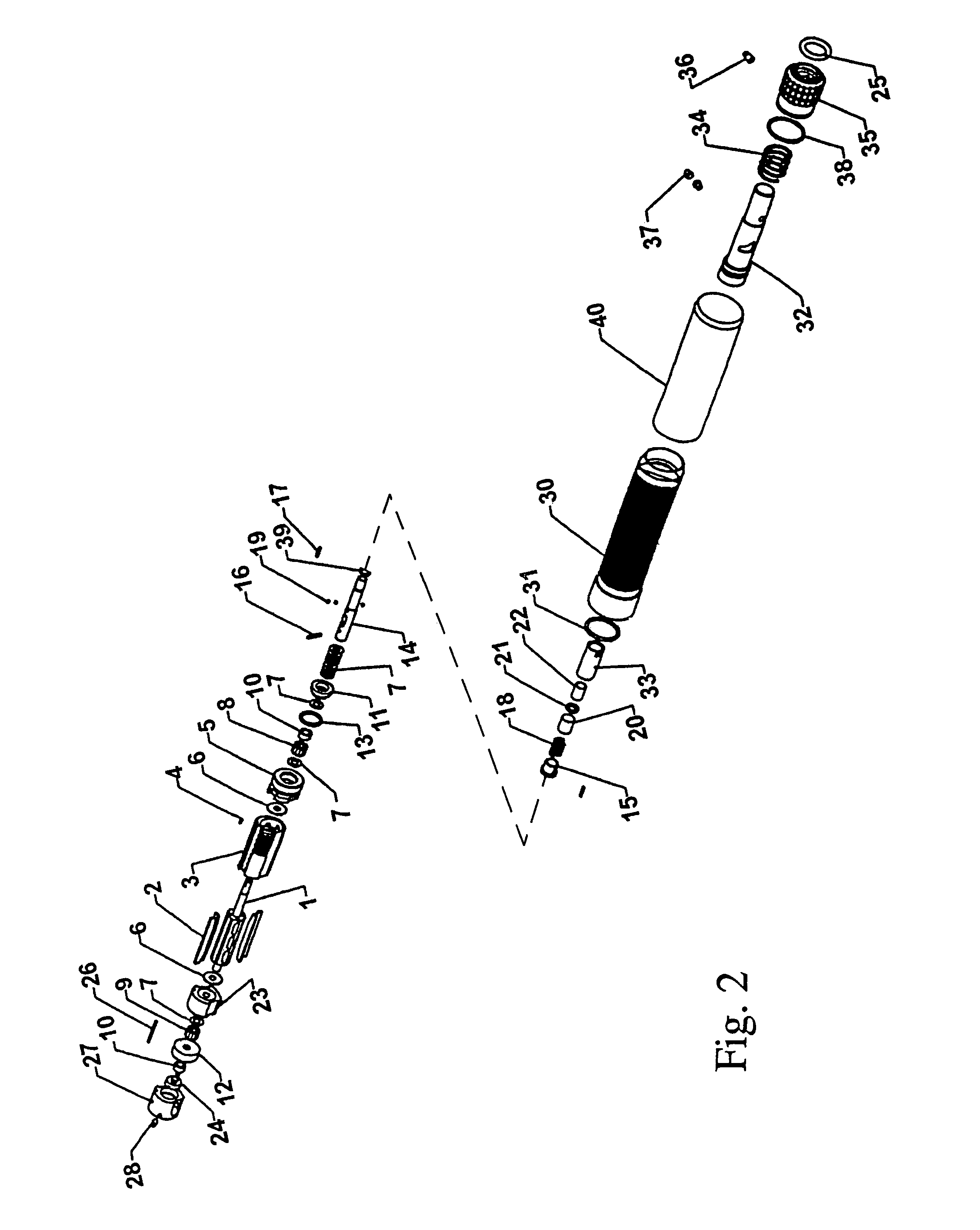
[0046]A better understanding of this invention can be had by referring to FIGS. 1 and 2 which show the motor generally indicated by reference numeral 50 and the attachment mechanism which is generally illustrated by reference numeral 52 including chuck means for removably attaching the attachment and for removably attaching the drill bit, burr and the various surgical instruments used with the motor (not shown). Inasmuch as the elements in the attachment mechanism 52 are well known for the sake of simplicity and convenience the details thereof are omitted hea...


PUM


Abstract

A surgical pneumatic motor is designed to be used with or without an MRI machine without affecting or influencing the magnetic characteristic of the MRI machine. The motor includes an improved vane motor with undercuts in the spindle to increase the power faces of the vanes and spindle itself, the holes in the cylinder are modified to increase the sealing area between the spindle. The inlet cylindrical holes and the cylinder holes and grooves are arranged to enhance the life . Wear of the edge of the vanes is decreased by the judicious location of the discharge holes. The bearings are cooled by bypassing a portion of cylinder air before re-entering the air. The noise is attenuated by a cris-cross plug in the hose the temperature of the handle is reduced by a serrated sleeve. Slipping discs in the seal serves to enhance seal life.

Description

[0001]This application claims the benefits under 35 U.S.C. § 119(e) of the U.S. provisional patent application 60 / 567,189 filed on Apr. 30, 2004.CROSS REFERENCES[0002]This application relates to the subject matter described in provisional patent application 60 / 567,188 filed on Apr. 30, 2004 . This invention also relates to U. S. patent application Ser. No. 10 / 306,256 filed on Nov. 27, 2002 entitled NEEDLE / ROLLER BEARING by Thomas E. Anspach and myself and identified as. Both of these applications are commonly assigned to The Anspach Effort, Inc and are incorporated herein by reference.FEDERALLY SPONSORED RESEARCH[0003]None.TECHNICAL FIELD[0004]This invention relates to pneumatic motors for use by surgeons for performing surgical procedures that are typical in general surgery, neurosurgery, endoscopic, arthroscopic and the like and more particularly to an improved pneumatic motor that has utility in connection with an MRI process.BACKGROUND OF THE INVENTION[0005]As one skilled in the...

Claims


Application Information

Patent Timeline
Patent Type & Authority Patents(United States)
IPC IPC(8): F01C21/00F03C2/00F04C15/00A61B17/00A61B17/16A61B17/24A61B17/32A61B19/00
CPCA61B17/1628A61B17/32002F01C1/344F01C21/06A61B2017/00544A61B2017/00911F04C2240/50F05C2251/125
Inventor DEL RIO, EDDY H.
Owner ANSPACH EFFORT
Why Eureka
Try Eureka