
Integrated machining module for processing workpieces and a method of assembling the same

a technology of integrated machining and workpieces, which is applied in the direction of isotope separation, combination devices, feed/discharge of settling tanks, etc., can solve the problems of inflexible manufacturing environment, inability to meet the requirements of manufacturing environment, and significant amount of time and mass of redundant operations, so as to improve inventive machining modules and reduce manpower requirements. , the effect of improving the inventive machining modul

Inactive Publication Date: 2009-05-05
DUERR ECOCLEAN GMBH
View PDF17 Cites 25 Cited by
  • Summary
  • Abstract
  • Description
  • Claims
  • Application Information

AI Technical Summary

Benefits of technology

The present invention provides an improved single machining module that can be easily assembled and moved to different remote locations for machining workpieces. The module includes a plurality of detachable machining tools, a coolant and filtration device, and a mist collection device. A manipulator, such as a multi-axial robot, can be connected to the module for processing the workpieces at each of the tools. The module is adaptable to be installed in various manufacturing environments and is flexible and re-configurable. It reduces manpower requirements, installation time, and the amount of space needed for installation. The invention also provides a single machining module that is integrated into existing buildings and can be re-tooled for future changes. Overall, the invention offers a new and efficient way for assembling and relocating a machining module in manufacturing environments.

Problems solved by technology

The collection system taught by the U.S. Pat. No. 5,980,735 to Bratten has to be re-configured and moved to adapt to various machining tools stationary located at manufacturing plants, which requires a significant amount of time and mass of redundant operations.
Although the prior machining systems are widely used in various industries today, these prior art designs have proven to be extremely complicated, and therefore non practicable, or have been non-flexible for the manufacturing environment.
In addition, these prior art machining systems require at least ten or fifteen persons and up to six and seven weeks of installation time to prepare the system for machining operations.

Method used


Image

  • Integrated machining module for processing workpieces and a method of assembling the same
  • Integrated machining module for processing workpieces and a method of assembling the same
  • Integrated machining module for processing workpieces and a method of assembling the same

Examples


Embodiment Construction

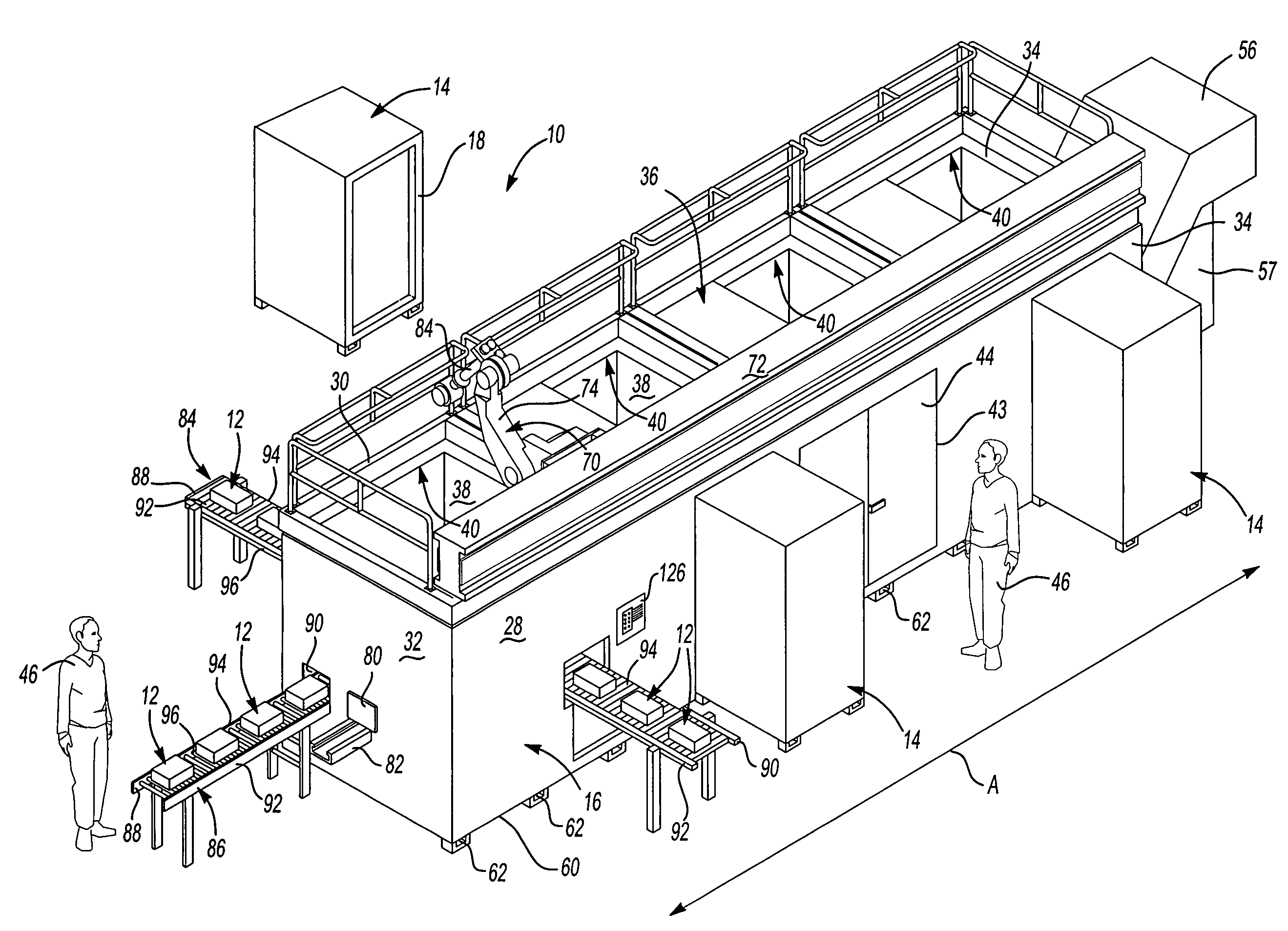
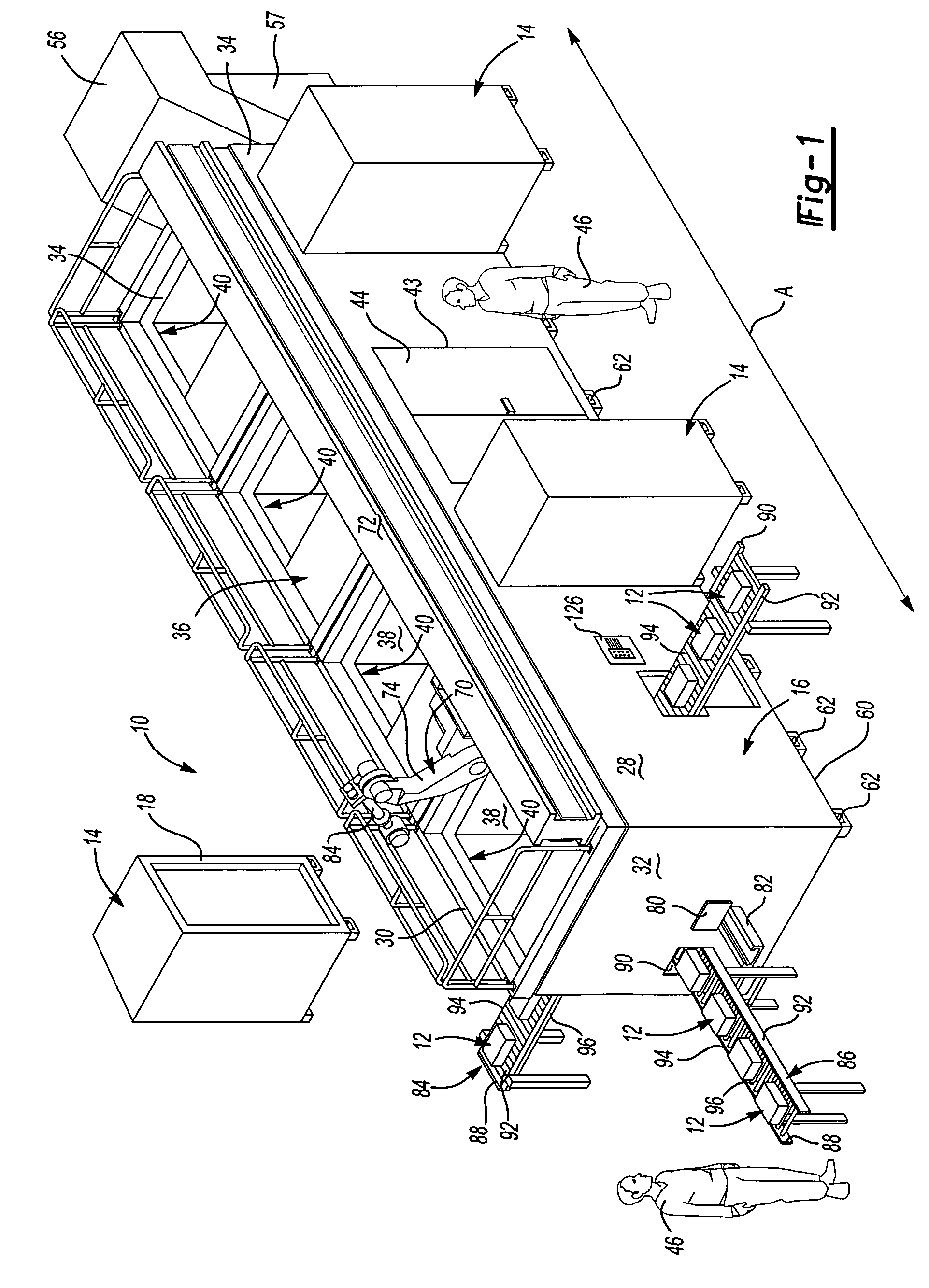
[0035]Referring to FIG. 1, an integrated machining module (the module) of the present invention, generally shown at 10, and is designed for machining workpieces, generally indicated at 12. Generally, the workpiece 12 is an iron cast or an injection molded and includes a housing for an automotive axle device, cylinder heads, crankcases or transmission housings, an engine block, and the like. The module 10 is adaptable to process an unfinished workpiece 12 which requires machining in order to create a finished product. The module 10 is used for various types of metal removal operations such as, for example grinding, drilling, milling, turning, sawing, thread cutting and the like required for finishing the workpiece 12.

[0036]The module 10 interfaces with a plurality machining tools, i.e. workstations, generally indicated at 14, detachably interconnected to a housing 16 as will be discussed in greater detail as the description of the module 10 proceeds. A tool (not shown) is disposed in...


PUM

PropertyMeasurementUnit
installation timeaaaaaaaaaa
interfaceaaaaaaaaaa
shapeaaaaaaaaaa

Abstract

A system for machining workpieces (12) and separating the chips from the workpieces (12) includes a plurality of workstations (14) detachably interconnected by a housing (16) and arranged along a processing path (A). A coolant and filtration device (56) extends through the workstations (14) and is adaptable for separating the chips from the workpieces (12). A mist collection device (54) is cooperable with the workstations (14) and the coolant and filtration device (56) for removing mist generated by the workstations (14) while machining the workpieces (12). The workstations (14) are interconnected with the mist collection device (54) and the coolant and filtration device (56) to form a single machining module (10) of various dimensions and configurations to be adaptable for various manufacturing environments.

Description

RELATED APPLICATIONS[0001]This non-provisional patent application claims the benefit of the provisional patent application Ser. No. 60 / 576,922 for a FLEXIBLE MACHINING MODULE, filed on Jun. 4, 2004, which is hereby incorporated by reference.BACKGROUND OF THE INVENTION[0002]1. Field of the Invention[0003]The subject invention relates to an automated machine tool for machining workpieces.[0004]2. Description of the Prior Art[0005]With advent of a modern technology machining operations play important role in manufacturing various parts, such as, for example, a housing for an automotive axle device, cylinder heads, crankcases or transmission housings. Each machining tool involves a lathe tool that generates circular sections by rotating the workpiece, so that a cutting tool can peel metal off, creating a smooth, round surface of the workpiece. A drill or punch press is used to remove metal in the shape of a hole. Other tools are used for various types of metal removal operations such as...

Claims


Application Information

Patent Timeline
Patent Type & Authority Patents(United States)
IPC IPC(8): C02F1/40B01L1/04B01D1/00B01D5/00B08B3/00B23Q7/14B23Q11/00B23Q37/00C02F1/00
CPCB01D5/0072B08B3/00B23Q7/1415B23Q11/0057B23Q37/00Y10S55/18Y10S55/29Y10S210/05Y02P70/10
Inventor JACKSON, MARK
Owner DUERR ECOCLEAN GMBH
Learn More