Shaft current control brush assembly with drainage

a brush assembly and shaft current technology, applied in current collectors, structural associations, dynamo-electric machines, etc., can solve the problems of increasing shaft induced currents, electric discharge machining, and buildup of charge on the shaft surface, so as to reduce the current of the shaft and the effect of effective conductive brush assembly

Active Publication Date: 2009-05-05
ILLINOIS TOOL WORKS INC
View PDF3 Cites 25 Cited by
  • Summary
  • Abstract
  • Description
  • Claims
  • Application Information

AI Technical Summary

Benefits of technology

[0013]An advantage of the present invention is providing an effective conductive brush assembly to reduce shaft current on rotating shafts without accumulating oils or other liquid contaminants that could interfere with operation and performance of the grounding assembly.
[0014]Another advantage of the present invention is providing a grounding assembly for electrical motor shafts that functions effectively for a prolonged period of time without service, maintenance or repair.
[0015]Still another advantage of the present invention is providing a conductive brush assembly that provides protection from contaminants for bearings near the assembly on a shaft on which the assembly and bearing are installed.
[0016]A still further advantage of the present invention is providing a drain for a grounding assembly on electric motors.
[0017]Other features and advantages of the invention will become apparent to those skilled in the art upon review of the following detailed description, claims and drawings in which like numerals are used to designate like features.

Problems solved by technology

A drawback to the use of AC motors with variable speed drives is that higher common mode voltage (CMV) is generated by the variable speed drive, which increases shaft induced currents.
While the motor is running, the bearings become more resistive to current flow, causing a buildup of charge on the shaft surfaces.
This discharge causes electric discharge machining (EDM), which can damage the surfaces of the bearing races and the balls in the bearing if the least resistant path is through the bearings.
Both the fusion crater and the particulate material in the bearing act to disturb the free flow rotation of the bearing, which can lead to physical damage and premature bearing failure.
Copper brushes can wear out rapidly, requiring frequent, periodic service and replacement.
Additionally, oxide build-up on the shaft and other barriers between the brushes and the shaft reduce the current flow and cause a burst of electrical energy across the brush and shaft.
Spring-loaded brushes also tend to vibrate due to alternating frictional relationships between the brush and the shaft surface.
Vibration of the brushes, from whatever cause, can result in undesirable sparking.
The accumulated liquid can interfere with the operation and performance of the grounding brush.
The contaminants can migrate to bearings on the shaft and can cause damage or deteriorated performance.
Removal of the assembly for periodic cleaning is time-consuming and may not be practical for substantially continuously operating equipment.

Method used


Image

  • Shaft current control brush assembly with drainage
  • Shaft current control brush assembly with drainage
  • Shaft current control brush assembly with drainage

Examples


Embodiment Construction

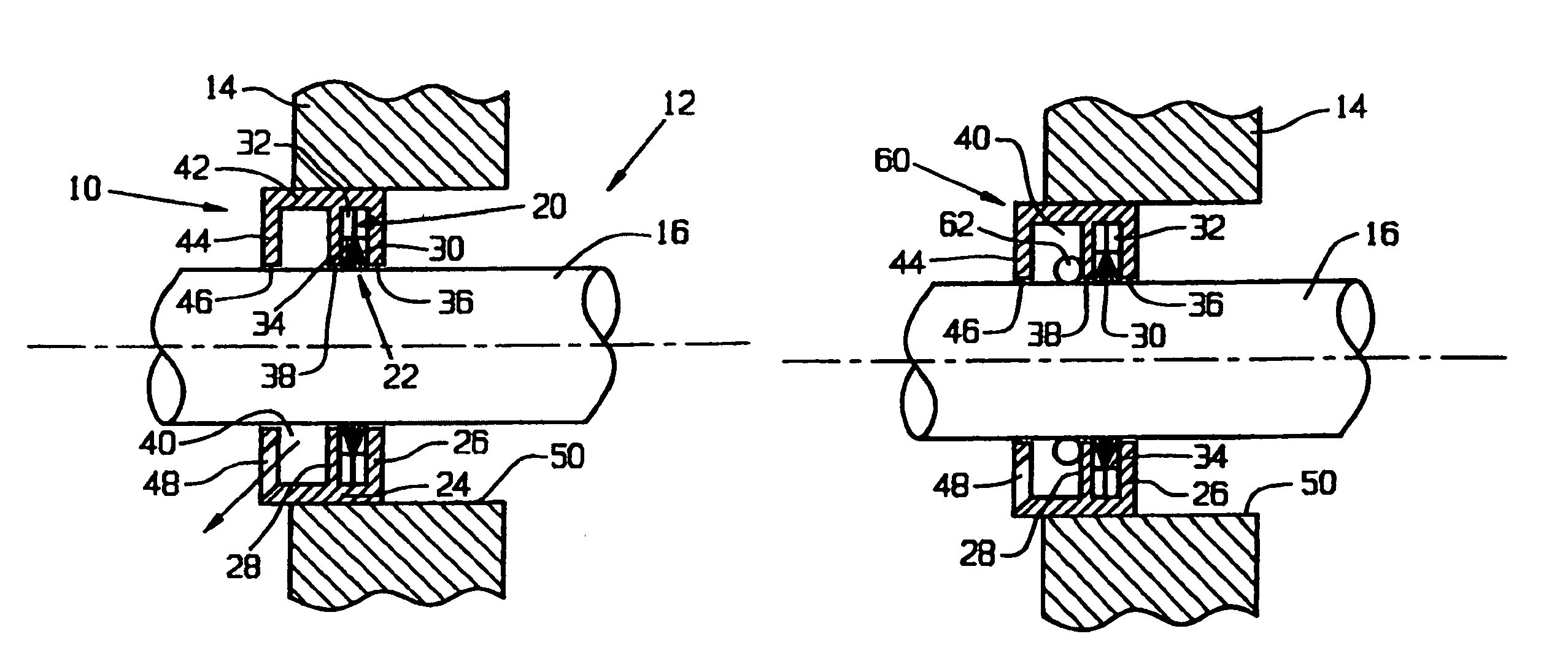
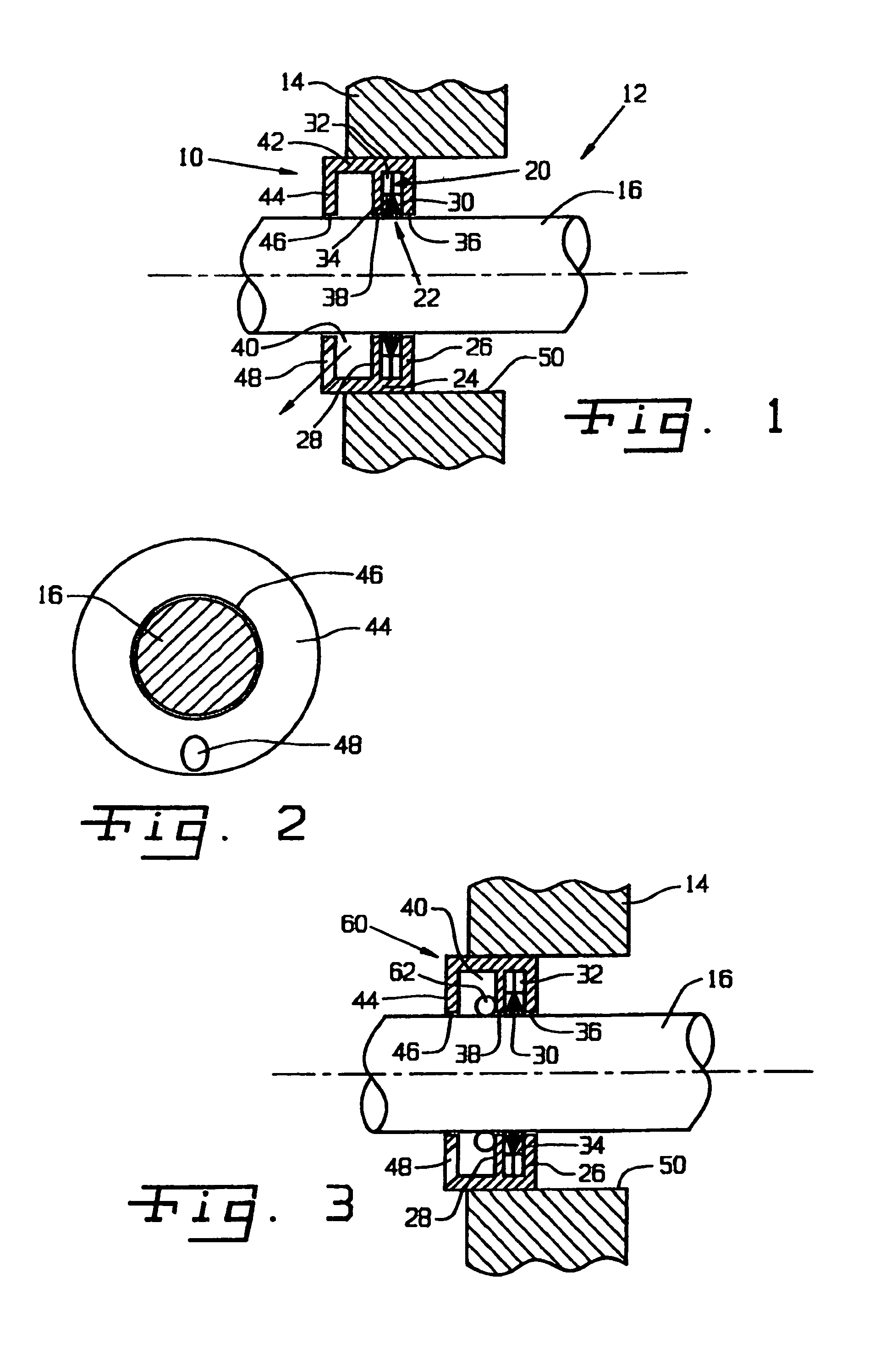
[0024]Referring now more specifically to the drawings and to FIG. 1 in particular, numeral 10 designates a shaft current control brush ring assembly in accordance with the present invention. Brush ring assembly 10 is installed on a motor 12 and specifically in a faceplate 14 of motor 12 for dissipating electrical charges that may build up on a shaft 16 of motor 12. It should be understood that brush ring assembly 10 can be provided in a variety of different sizes for use in motors of different types and on shafts 16 of different diameters.

[0025]Brush ring assembly 10 is of generally annular shape, encircling shaft 16. Brush ring assembly 10 is secured to faceplate 14 and is operatively arranged between shaft 16 and faceplate 14 to dissipate static or other charges that build on motor shaft 16 during operation of motor 12.

[0026]Brush ring assembly 10 includes an annular channel 20 and a brush assembly 22 disposed therein. Channel 20 includes a cylindrical outer band 24 with an inner ...


PUM


Abstract

A shaft current control brush ring assembly includes a channel and a brush ring assembly secured within the channel. A drain is provided to direct liquids and contaminants away from said brush ring assembly.

Description

CROSS-REFERENCE TO RELATED APPLICATIONS[0001]The present application claims the benefits of U.S. Provisional Application 60 / 709,021 filed Aug. 17, 2005FIELD OF THE INVENTION[0002]The present invention relates generally to grounding assemblies, and, more particularly, to grounding assemblies for motor shafts, turbine shafts and other rotating shafts conductively linked to components that create an electrical charge, or that may experience a build-up of electrical charge.BACKGROUND OF THE INVENTION[0003]Shaft induced electrical current is experienced in electric motors, and commonly in three-phase motors driven by variable speed drives. Variable speed drives utilize pulse width modulation technology to vary the speed of AC motors, thereby allowing use of less-expensive AC motors in applications where more expensive DC motors had been used previously. A drawback to the use of AC motors with variable speed drives is that higher common mode voltage (CMV) is generated by the variable spee...

Claims


Application Information

Patent Timeline
Patent Type & Authority Patents(United States)
IPC IPC(8): H02K5/10
CPCH02K11/0089H02K11/40
Inventor OH, HIEYOUNG W.
Owner ILLINOIS TOOL WORKS INC
Why Eureka
Try Eureka