Linear drive apparatus

a technology of linear drive and drive shaft, which is applied in the direction of motor/generator/converter stopper, dynamo-electric converter control, instruments, etc., can solve the problems of inability to apply wet processing of small objects, inability to detect an accurate position, and inability to affect the magnetic scale, etc., to achieve high precision processing of precision parts, high precision processing, and high efficiency

Inactive Publication Date: 2009-05-05
FANUC LTD
View PDF12 Cites 16 Cited by
  • Summary
  • Abstract
  • Description
  • Claims
  • Application Information

AI Technical Summary

Benefits of technology

[0009]In view of the above-described problem, it is an object of the present invention to provide a linear drive apparatus having a magnetic measurement unit that is capable of reducing the influence of an external magnetic field on detection of the position of a movable member.
[0011]In accordance with the invention, since the direction of the opposition of the magnetic scale and the detector intersects the direction of magnetic force of the surrounding external magnetic field, the direction of the magnetization of the magnetic scale and the direction in which the detector detects the magnetic force intersect the direction of the magnetic force of the surrounding external magnetic field, so that interference of the external magnetic field with the detected signal is reduced. Therefore, even in the presence of an external magnetic field, the relative position of the slider can be measured accurately by the magnetic measurement unit and positional precision of the linear drive apparatus can be improved.
[0013]In accordance with the invention, since the opposing direction of the magnetic scale and the detector is the direction of the outer circumference of the guide, even when the magnetic scale is used in an environment in which the guide generates a magnetic force, the direction of the magnetization of the magnetic scale and the direction in which the detector detects the magnetic force intersect the lines of magnetic force, so that interference of the external magnetic field with the detected signal is reduced. Therefore, even in the presence of an external magnetic field, the relative position of the slider can be measured accurately by the magnetic measurement unit and the positional precision of the linear drive apparatus can be improved.
[0015]In accordance with the invention, the opposing direction of the magnetic scale and the detector is generally in a direction perpendicularly intersecting the radial lines of magnetic force generated in radial direction of the permanent magnet or the center bar of the magnetic body. Therefore, the relative position of the slider can be accurately measured even in the presence of a strong magnetic force.
[0017]In accordance with the invention, the influence of vibration due to the rigidity of the processing machine, etc. can be reduced so as to permit high precision processing of precision parts. A synergistic effect with a linear motor mechanism will permit highly efficient and high precise processing.

Problems solved by technology

However, there are problems with such optical measuring units in that they are inappropriate for measurement, especially for in-process measurement, in a degraded environment where coolant or chips are present, and that they cannot be applied to wet processing of small articles.
However, when the magnetic scale is mounted to a slider or the like that is driven by a linear motor mechanism, the magnetic scale is likely to be affected by the magnetic force generated by a coil or a magnet, and this may lead to a problem of detecting an accurate position.
Therefore, a magnetic measurement unit including a magnetic scale has to be mounted at a position sufficiently far away from a coil or magnet, so that precision higher than a certain level cannot be achieved in detecting a position.
These methods, however, lead to another problem that, since a magnetic shield or a coil is added to the apparatus, it becomes difficult to reduce the size or weight of the apparatus.

Method used


Image

  • Linear drive apparatus
  • Linear drive apparatus
  • Linear drive apparatus

Examples


Embodiment Construction

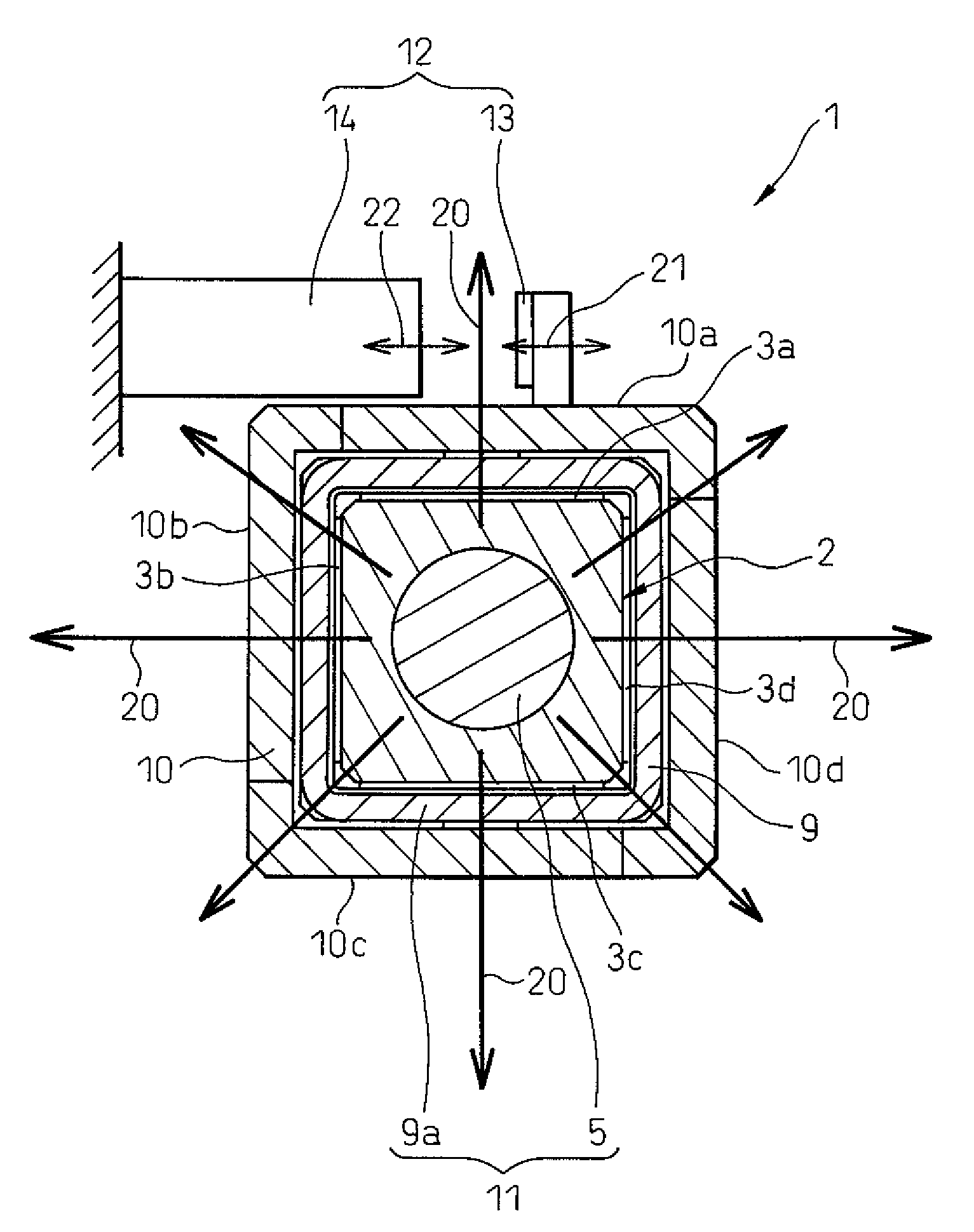
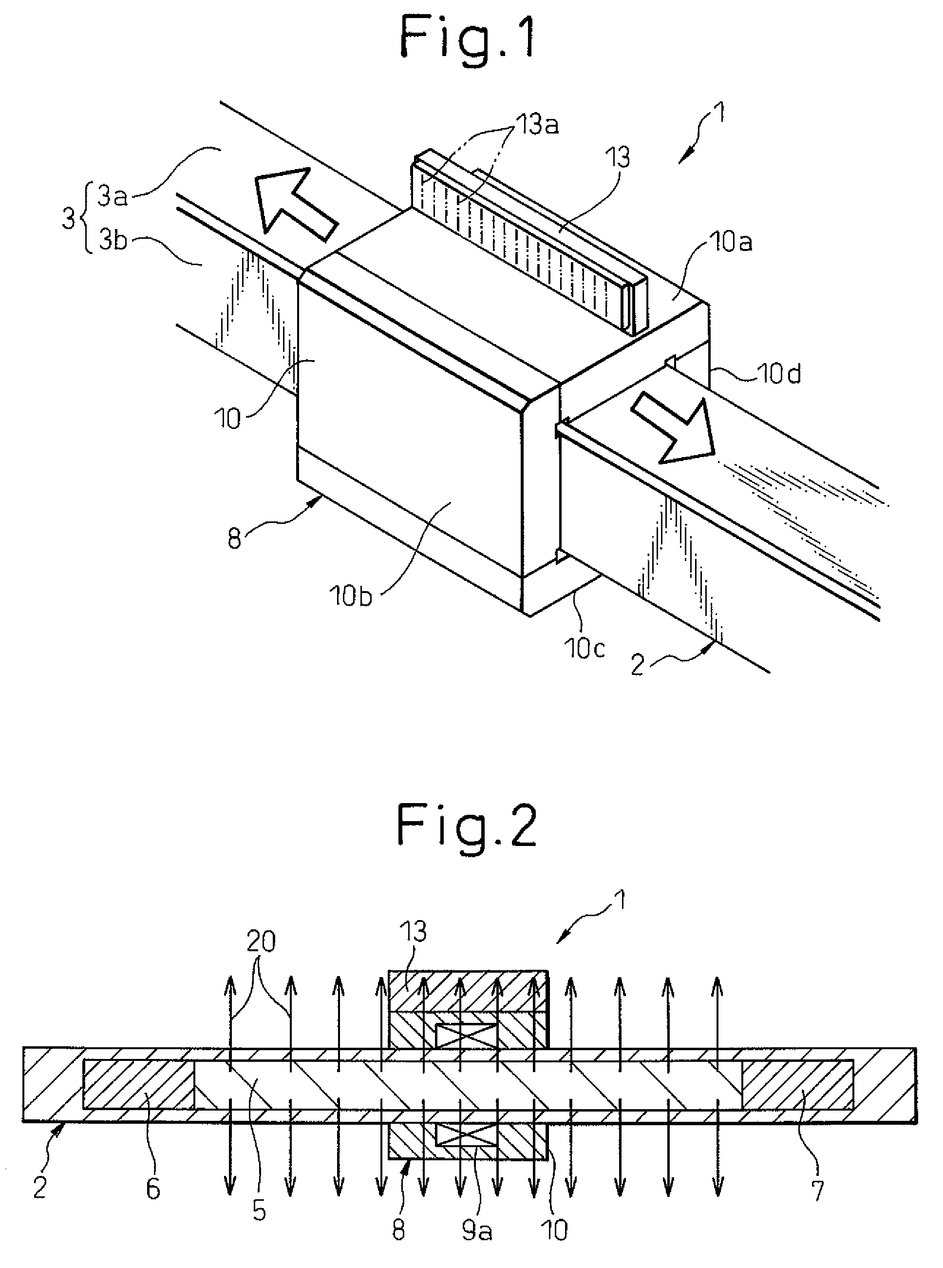
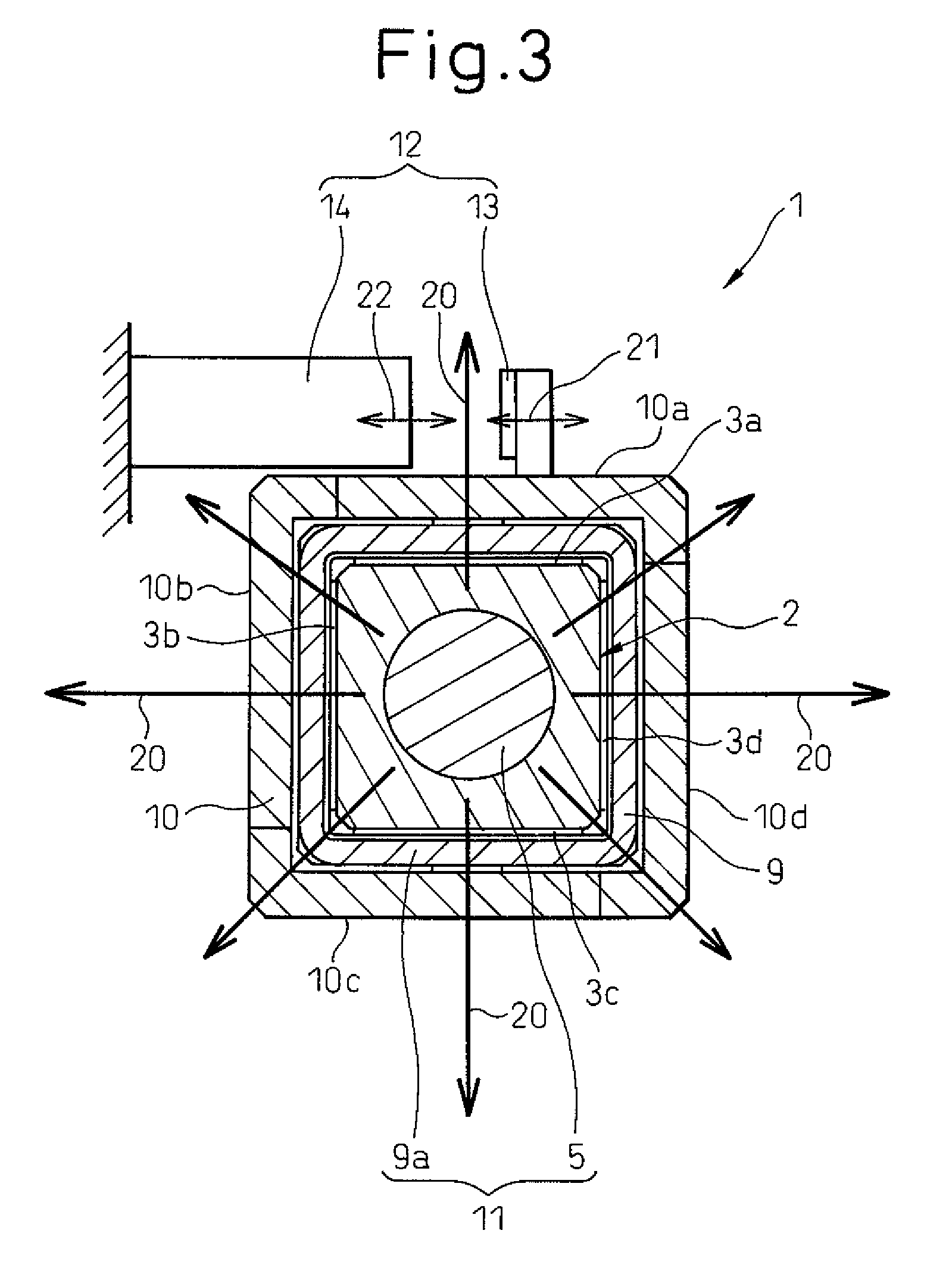
[0022]A linear drive apparatus according to the present invention will be now described in detail with reference to the drawings. A linear drive apparatus 1 of the present embodiment is comprised of a base (not shown), a guide 2 fixed to the base, a slider 8 guided by the guide 2 to be moved in relative movement, a linear motor mechanism 11 that linearly drives the slider 8 by means of magnetic interaction of the slider 8 and the guide 2, a magnetic measurement unit 12 for measuring the relative position of the slider 8, and a pneumatic bearing for supporting the slider 8 by supplying compressed air into the gap between the opposing surfaces of the guide 2 and the slider 8.

[0023]As shown in FIG. 1, the guide 2 has a rectangular shaped cross section and extends horizontally in a straight line from one side to the other side of the base. The outer surfaces 3 of the guide 2, that is, the upper and lower surfaces, and both side surfaces, form pairs of bearing surfaces 3a to 3d. Each of ...


PUM


Abstract

A linear drive apparatus comprising: a guide having an internal body; a slider moved along the guide, a driving mechanism for generating a driving force by magnetic interaction of the slider with the guide so as to linearly drive the slider; and a magnetic measurement unit having a magnetic scale and a detector which are opposed to each other and change a relative position relative to each other in order to obtain the relative position of the slider relative to the guide, wherein an opposing direction of the magnetic scale and the detector is the direction of the outer circumference of the guide, and the detector detects a signal from the magnetic scale in accordance with the relative position of the slider, whereby the relative position of the slider is obtained.

Description

CROSS REFERENCE TO RELATED APPLICATION[0001]The present application claims priority of Japanese Patent Application No. 2006-036802 filed on Feb. 14, 2006, disclosure of which is incorporated, by reference, in its entirety.BACKGROUND OF THE INVENTION[0002]1. Field of the Invention[0003]The present invention relates to a linear drive apparatus that is used in a machine tool or a measuring apparatus having a guide, a slider that is moved along the guide by a driving mechanism, and a magnetic measurement unit for measuring the relative position of the slider relative to the guide.[0004]2. Related Art[0005]In a linear drive apparatus comprising a guide and a slider that is moved along the guide by a driving mechanism, an optical measurement unit is generally used to measure the relative position of the slider relative to the guide. Such an optical measurement unit generally has a light source, an optical scale, and a light receiving section. However, there are problems with such optical ...

Claims


Application Information

Patent Timeline
Patent Type & Authority Patents(United States)
IPC IPC(8): H02K41/00G01D5/12G01D5/245
CPCF16C29/00H02K41/031G01D5/145H02K11/0021H02K11/215
Inventor KAWAI, TOMOHIKOEBIHARA, KENZOMATSUURA, OSAMU
Owner FANUC LTD
Why Eureka
Try Eureka