Method and device for controlling a charging device of an internal combustion engine during a charging mode

a charging mode and charging device technology, applied in the direction of electrical control, process and machine control, instruments, etc., can solve the problems of increasing fuel consumption, unable to easily set a predefined dynamic response, and characteristics maps are not readily used, so as to reduce and increase the mass flow rate of air into the cylinder

Active Publication Date: 2009-05-05
ROBERT BOSCH GMBH
View PDF6 Cites 4 Cited by
  • Summary
  • Abstract
  • Description
  • Claims
  • Application Information

AI Technical Summary

Benefits of technology

[0006]Therefore, an object of the present invention is to provide a method and a device for setting a mass flow rate of air to be provided in a charging mode in an internal combustion engine, with the aid of which it is possible to reproducibly set the air charge into the cylinder without increasing the fuel consumption.
[0009]In contrast to control of the charging device as a function of operating point, the present invention provides an air-charge control system, with the aid of which an adjustable dynamic air-charge response may be attained. The dynamic charge response ensues from the fact that in the event of a requested torque where the engine is operated in the charging mode, i.e., in an operating range of the internal combustion engine in which the air charge is no longer controlled via the throttle valve, but only via the charging device, a mass flow rate predetermined by the dynamic charge response is requested via the charging device, the mass flow rate being higher than is necessary in a steady state, i.e., than what is currently being requested by the internal combustion engine as a setpoint mass flow rate of air. This results in the pressure necessary for setting the actual mass flow rate of air into the cylinders being able to be reached more rapidly than in the case of previous control systems. In addition, this allows the dynamics of reaching the specific pressure in the induction pipe to be rendered reproducible, which means that the same response of the engine may be obtained in any engine state.
[0010]In addition, the pressure in the induction pipe may be set by adjusting the mass flow rate of supplied air. As long as the predefined dynamic response is more rapid than the characteristic dynamic response of the system, in order to increase the mass flow rate of air into the cylinder, the mass flow rate of air supplied, for example, via the charging device during a particular period of time may be selectively increased with respect to the necessary setpoint mass flow rate of air into the cylinder as a function of physics and requested dynamic response, and in order to reduce the mass flow rate of air into the cylinder, the mass flow rate of supplied air may be reduced during a particular period of time in comparison with the setpoint mass flow rate of air into the cylinder.
[0017]The control unit is preferably designed to adjust the mass flow rate of supplied air in order to set the pressure in the induction pipe; to increase the mass flow rate of air supplied via the charging device during a specific period of time with respect to the mass flow rate of air into the cylinder as a function of the desired dynamic charge response characteristic, in order to increase the mass flow rate of air into the cylinder; and to reduce the mass flow rate of air supplied via the charging device during a specific period of time with respect to the mass flow rate of air into the cylinder, in order to decrease the mass flow rate of air into the cylinder.

Problems solved by technology

This is complicated by the fact that not only does the throttle valve have to be set to allow the desired mass to flow into the engine, but also that the volume of the vessel between the throttle valve and engine, the so-called induction pipe, must be filled or emptied as rapidly as possible, i.e., a desired induction-pipe pressure must be built up or reduced.
To this end, however, it must be ensured that a sufficiently higher pressure (charge-air pressure) is always available in front of the throttle valve than is intended to be set in the induction pipe in back of the throttle valve, which means that the fuel consumption is increased.
Consequently, the characteristics map may also not be readily used for setting a predefined dynamic response characteristic of the charging in the pressure-charged region.

Method used


Image

  • Method and device for controlling a charging device of an internal combustion engine during a charging mode
  • Method and device for controlling a charging device of an internal combustion engine during a charging mode
  • Method and device for controlling a charging device of an internal combustion engine during a charging mode

Examples


Embodiment Construction

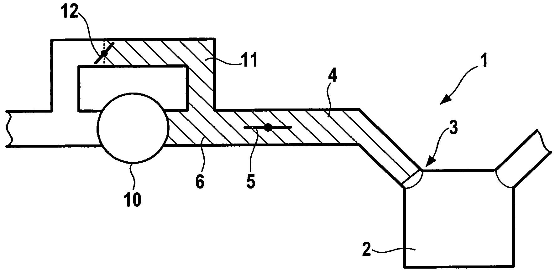
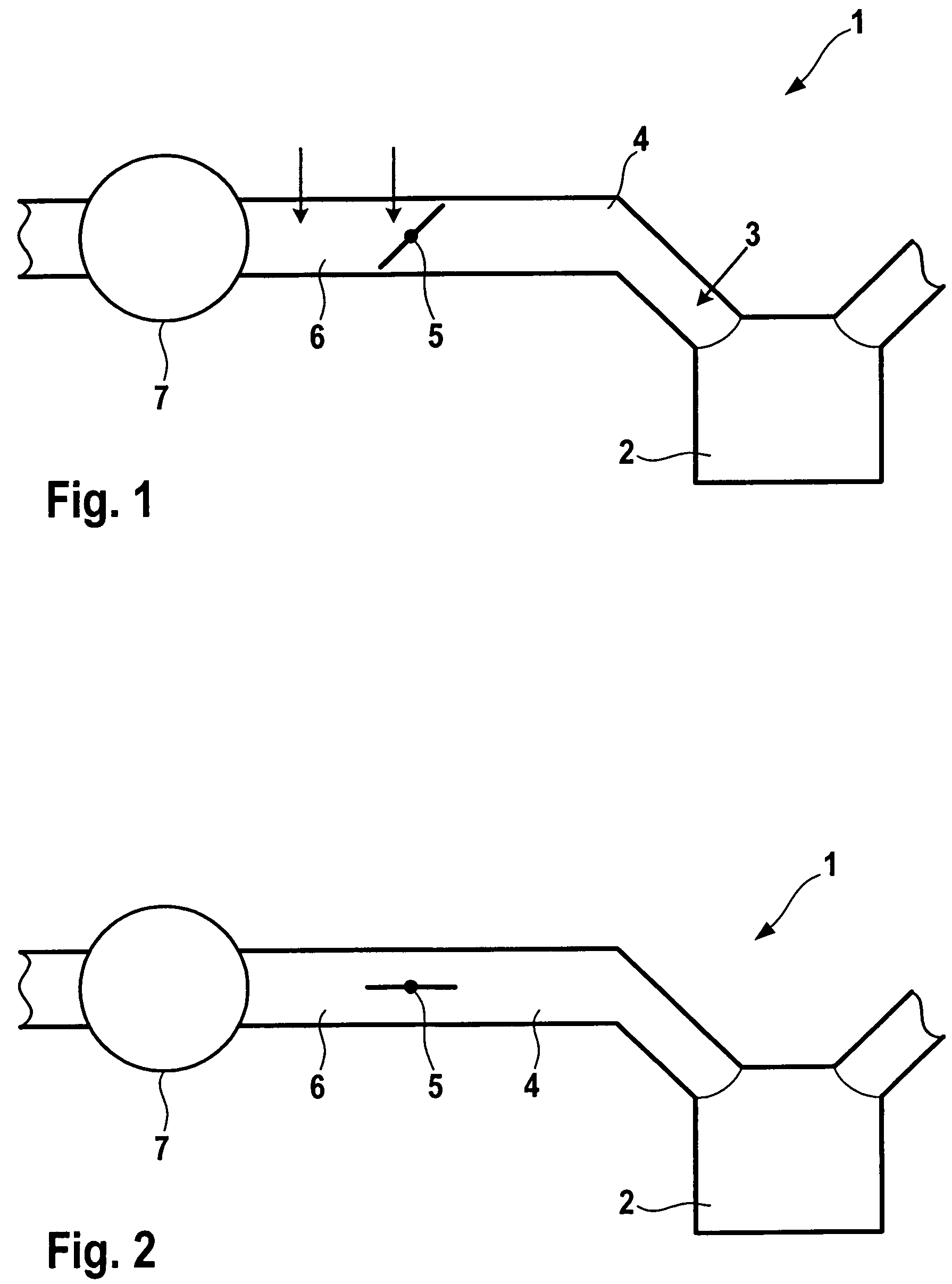
[0022]FIGS. 1 and 2 show schematic representations of two operating modes of an internal combustion engine 1. Internal combustion engine 1 has a row of cylinders 2, of which only one is shown for reasons of clarity. A mass flow rate of air able to flow into cylinder 2 is provided to cylinder 2 via an intake valve 3, in order to set an air charge there. The mass of air flowing into cylinder 2 is provided in front of intake valve 3 via an induction pipe 4, by providing or building up a specific pressure there in order to effect, in this manner, the desired mass flow rate of air into cylinder 2.

[0023]The internal combustion engine may be operated in two operating modes, in a throttle-valve mode and in a charging mode. In the throttle-valve mode, as is represented in FIG. 1, the pressure in induction pipe 4 is adjusted via the position of throttle valve 5, which reduces a higher pressure in a charge-air line 6 situated in front of the throttle valve to the desired pressure in induction ...


PUM


Abstract

A method for setting a mass flow rate of air to be provided in a charging mode; in the charging mode (where a throttle valve is open), the pressure prevailing in an induction pipe only being set via an adjustable mass flow rate of supplied air; a requested torque corresponding to a mass flow rate of air into a cylinder, the mass flow rate of air into the cylinder being adjustable via the pressure in the induction pipe; to set the mass flow rate of air into the cylinder, the pressure in the induction pipe being adjusted by a control system in accordance with a specifiable dynamic charge response characteristic.

Description

BACKGROUND INFORMATION[0001]To operate internal combustion engines, fuel is injected into cylinders and a corresponding mass flow rate of air is supplied. The mass flow rate of air into the cylinders, which represents the so-called air charge of the cylinders, is adapted to the specific engine state. A setpoint air charge of the cylinders is determined by a torque requested, for example, by the driver; with the aid of a throttle-valve control system, the mass flow rate of air into the engine being controlled, and it being ensured that the actual air charge follows the setpoint air charge as effectively as possible. This is complicated by the fact that not only does the throttle valve have to be set to allow the desired mass to flow into the engine, but also that the volume of the vessel between the throttle valve and engine, the so-called induction pipe, must be filled or emptied as rapidly as possible, i.e., a desired induction-pipe pressure must be built up or reduced.[0002]The vo...

Claims


Application Information

Patent Timeline
Patent Type & Authority Patents(United States)
IPC IPC(8): F02D41/18
CPCF02B37/16F02D41/0007F02D2041/1431Y02T10/144Y02T10/12
Inventor MILOS, KRISTINAREUSCHENBACH, LUTZWEGENER, SABINECHOUK, LANOUARMENOLD, PATRICK
Owner ROBERT BOSCH GMBH
Why Eureka
Try Eureka