Writing implement

a technology of writing implements and writing handles, which is applied in the direction of writing connectors, propelling pencils, brushes, etc., can solve the problems of not being able to satisfactorily handle the weight distribution, not giving a hand gripping the writing implement satisfactory balance and stability, and ill-balanced writing implements, etc., to achieve satisfactory stability, satisfactory writing operation, and good balance

Inactive Publication Date: 2009-05-12
PILOT PEN CO LTD
View PDF14 Cites 2 Cited by
  • Summary
  • Abstract
  • Description
  • Claims
  • Application Information

AI Technical Summary

Benefits of technology

[0011]Accordingly, it is an object of the present invention to solve problems in the foregoing prior art and to provide a writing implement that is well-balanced and capable of giving a satisfactory sensation of stability to the hand gripping the writing implement, of being handled in smooth, minute, reciprocating, turning motions for a satisfactory writing operation.
[0012]The inventors of the present invention studied the balance and stability of writing implements during writing operations and have found that a hand grips a writing implement by placing the tips of the thumb, the first finger and the second finger on a part a of the writing implement and resting a part b of the writing implement at the joint of the thumb and the first finger as shown in FIG. 14, and the writing implement gives satisfactory sensations of balance and stability during writing operations if the writing implement has its center of gravity at a point between the parts a and b and the most part of the weight of the writing implement is concentrated on a part of the writing implement between the parts a and b.
[0013]Generally, a writing implement with a projecting writing element, such as a mechanical pencil, a ballpoint pen, a fountain pen or a marker, has a length between 120 and 180 mm and the tip part of the writing implement is tapered to facilitate seeing the tip of the writing element. Therefore, the part a on which the tips of the thumb, the first finger and the second finger are placed is behind the tapered tip part. Although different writing implements have tip parts of different shapes, respectively, the length of the tip part including the writing element is between about 15 and about 20 mm and hence the part a is at a distance between 15 and 20 mm backward from the tip of the writing element. Although dependent on the size of the hand gripping the writing implement, the part b that rests on the joint of the thumb and the first finger is at least a short distance behind the middle part of the writing implement. Consequently, the writing implement is able to give satisfactory sensations of balance and stability when the writing implement has its center of gravity at a position between a part at 20 mm from the tip of the writing element and the middle part and has weight concentrated on a part near the center of gravity.

Problems solved by technology

However, the writing implement constructed simply so that the center of gravity is in the middle region of the barrel could not give a hand gripping the writing implement satisfactory sensation of balance and stability.
A writing implement designed to place the center of gravity in its middle region, ignoring weight distribution is not necessarily capable of being satisfactorily handled in minute, reciprocating, turning motions.
However, such a writing implement is ill-balanced and is unable to give a satisfactory sensation of stability to the hand gripping the writing implement.
When the writing implement is gripped by a hand in a tilted position for writing, the metallic parts respectively having high specific weights destroy the balance and spoil the stability of the writing implement.
When the front and the back part remote from the center of gravity are formed from metallic parts respectively having high specific weights, the writing implement has a large rotational inertia and cannot be smoothly operated in minute, reciprocating, turning motions.
However, it was found that the facility of handling the writing implement in minute, reciprocating, turning motions cannot be improved simply by setting the axis of turning of the writing implement at the center of gravity because the writing implement consists of many component parts and the rotational inertia of the writing implement is the sum of the respective rotational inertias of the component parts.

Method used


Image

  • Writing implement
  • Writing implement
  • Writing implement

Examples


first embodiment

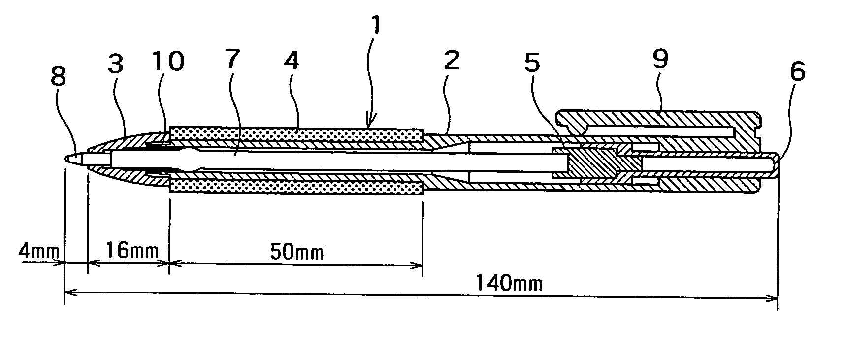
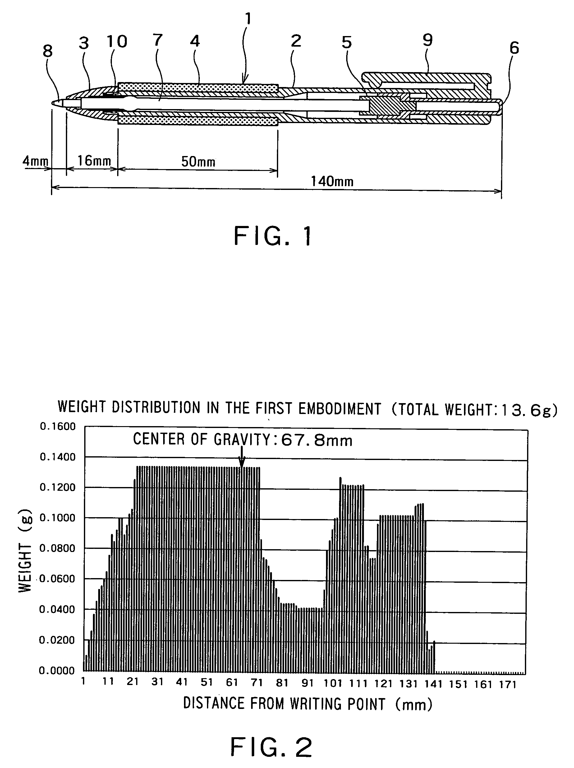
[0039]Referring to FIG. 1 showing a writing implement 1 in a first embodiment according to the present invention, a barrel 2 of a polypropylene resin, i.e., a resin having a low specific gravity, has a reduce gripping part having an outer diameter smaller than that of other parts. A grip member 4 of a silicone rubber having a high specific gravity of about 1.2 gf / cm3 is put on the gripping part of the barrel 2. This writing implement 1 is a push-button ballpoint pen. A barrel cap 3 formed of a PC resin (polycarbonate resin) is screwed in the front end of the barrel 2. A ballpoint pen refill is inserted in the barrel 2 and is pushed backward by a coil spring formed by coiling a hard steel wire. The ballpoint pen refill has a cartridge tube 7 of a PP resin (polypropylene resin) containing an oil ink, and a ballpoint pen tip 8 having a socket rotatably holding a tungsten carbide ball and attached to the front end of the cartridge tube 7.

[0040]The barrel 2 is provided in its inner surfa...

third embodiment

[0047]A writing implement 21 in a third embodiment according to the present invention shown in FIG. 6 is a capped ballpoint pen. The writing implement 21 has a barrel 22 having a gripping part, a grip member 24 put on the gripping part of the barrel 22, a weight adjusting part G′ put on the gripping part of the barrel 22 to localize most of the weight of the writing implement 21 in a part between a position at 20 mm from a writing point and a position corresponding to the middle of the overall length of the writing implement 21, and a cap 25 integrally provided with a clip 26 and put on a back part of the barrel 2. The weight adjusting part G′ is formed of aluminum of about 2.7 gf / cm3 in specific gravity. The cap 25 is formed of a polypropylene resin. The writing implement 21 is 17.1 gf in total weight and 140 mm in overall length. The writing implement 21 has its center of gravity at a position at 67.4 mm from the writing point and a rotational inertia I of about 26,000 gf·mm2 abou...

second embodiment

[0049]FIG. 8 shows a conventional push-button ballpoint pen (writing implement) 101 similar in construction to the writing implements in the first and the The push-button ballpoint pen 101 has a barrel cap 103 formed of brass, a barrel 2 not provided with any weight adjusting member, and an elastic tube 104 formed of a silicone rubber in a small thickness and put on the barrel 2. The weight of the push-button ballpoint pen 101 is distributed in a weight distribution curve shown in FIG. 9. The push-button ballpoint pen 101 has its center of gravity at a position at 54.9 mm from the writing point, and the weight of a part between a position at 20 mm from the writing point and a position corresponding to the middle of the overall length thereof, i.e., a position at 70 mm from the writing point, is about 31% of the total weight of the push-button ballpoint pen 101, i.e., a weight not greater than 50% of the total weight of the push-button ballpoint pen 101.

[0050]More concretely, the pu...


PUM


Abstract

A writing implement including a plurality of component parts A, B, C, etc. is satisfactory in balance and stability during writing operations and can be smoothly handled for minute, reciprocating, turning motions during writing operations. The writing implement including the component parts A, B, C etc. has its center of gravity in a part thereof between a position at 20 mm from the tip of a projected writing element and a position corresponding to the middle of the overall length thereof, and the weight of the part thereof between the position at 20 mm from the tip of the projected writing element and the position corresponding to the middle of the overall length is not less than 50% of the total weight of the writing implement.

Description

TECHNICAL FIELD[0001]The present invention relates to a writing implement including a plurality of writing parts.BACKGROUND ART[0002]Techniques relating to the center of gravity of a writing implement have been proposed. For example, a writing implement is disclosed in JP 2001-270281 A (Patent document 1) having its center of gravity in a middle region of a barrel having front, middle and back regions and capable of being stably handled in minute, reciprocating, turning motions for writing.[0003]The inventors of the present invention conducted studies to develop a writing implement that can be easily handled in minute, reciprocating, turning motions and found that a writing implement makes minute, reciprocating, turning motions to move its writing point up and down as shown in FIG. 3 when the writing point is shifted from the end of the last stroke of one letter to a position to start writing the next letter. A writing implement capable of being easily handled in minute, reciprocati...

Claims


Application Information

Patent Timeline
Patent Type & Authority Patents(United States)
IPC IPC(8): B43K29/00B43K3/00B43K5/00B43K7/00B43K8/00B43K21/00B43K23/008B43K24/08
CPCB43K5/005B43K7/005B43K8/003B43K21/006B43K23/008B43K24/084B43K29/00B43K3/00B43K7/00
Inventor KOBAYASHI, YOSHIHIROIWABUCHI, YOUICHI
Owner PILOT PEN CO LTD
Why Eureka
Try Eureka