Multicast packet control apparatus
a packet control and multi-cast technology, applied in multiplex communication, digital transmission, data switching networks, etc., can solve the problems of increasing the update time of user information, and it is difficult to perform correct user management including accounting services, and achieves high load
- Summary
- Abstract
- Description
- Claims
- Application Information
AI Technical Summary
Benefits of technology
Problems solved by technology
Method used
Image
Examples
first embodiment (
3-1. First Embodiment (when Response Reports are Sent Simultaneously)
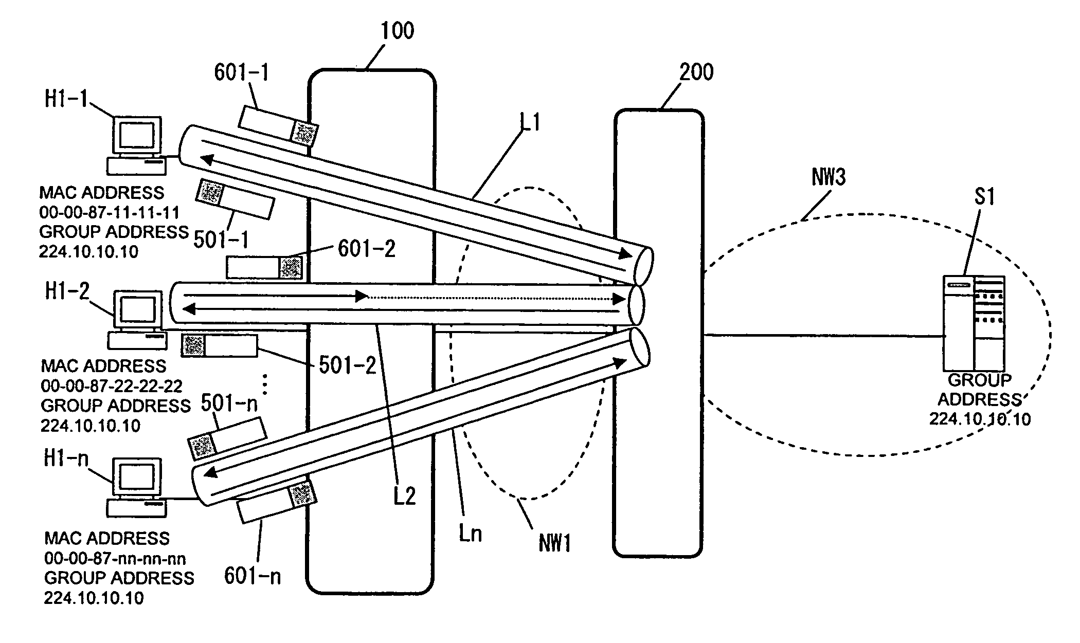
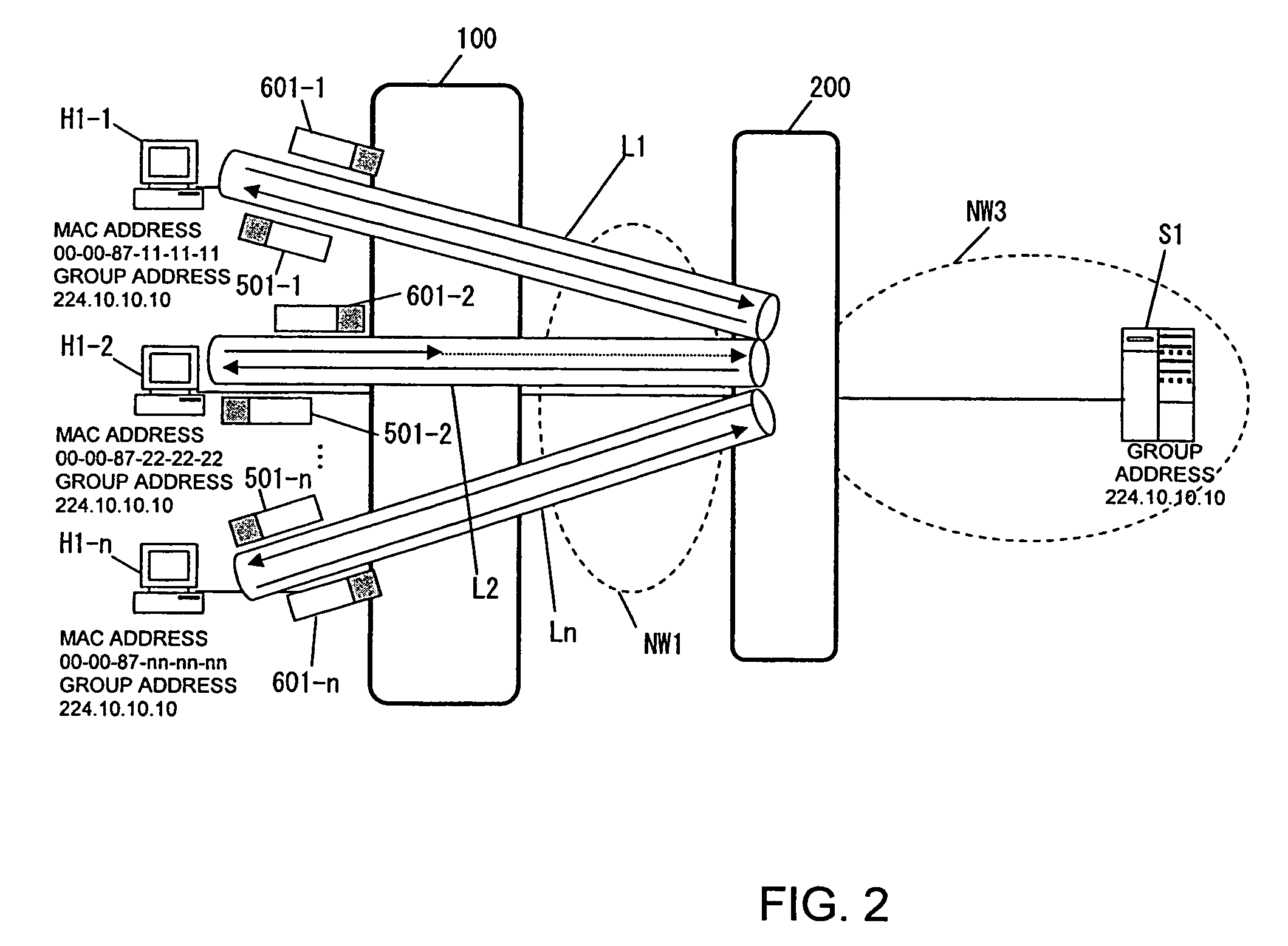
[0098]When the user terminals H1-1 to H1-n return response report packets simultaneously in response to join confirmation made by the router 200, the Layer 2 switch 100 operates as described below.
[0099]The router 200 broadcasts join confirmation packets 500-1 to 501-n to the user terminals H1-1 to H1-n, then the user terminals H1-1 to H1-n return response report packets 601-1 to 601-n simultaneously. The response report packets reach the channel interfaces 100-1 of the Layer 2 switch 100 and are transferred to the channel interface control block 100-2. The channel interface control block 100-2 transfers the received packets to the reception buffer 100-7-2 and makes an interrupt to notify the processor 100-3 that the packets have been received. Receiving the interrupt, the processor 100-3 reads the packets from the reception buffer 100-7-2 and handles the packets in accordance with the flow chart shown in FIG. 13.
[...
second embodiment (
3-2. Second Embodiment (when Join Requests or Leave Statements are Sent Simultaneously)
[0108]Described below will be a case in which the user terminals H1-1 to H1-n send join requests or leave statements simultaneously, independently of join confirmation sent from the router 200.
[0109]The join requests packets 605-1 to 605-n sent simultaneously from the user terminals H1-1 to H1-n are processed in accordance with the flow chart shown in FIG. 14 (in steps 900 to 903). The processor 100-3 checks the transfer limitation table 100-4-1, compares the monitored utilization rate with the value specified in the table, and determines whether a limitation is needed (in step 902) as in the first embodiment. If there are too many packets, packet transfer from the IGMP transmission buffer 100-7-3 to the router 200 is limited (in step 820). The processor 100-3 enlarges the IGMP transmission buffer 100-7-3 in accordance with the transmission buffer size modification table 100-4-3 (in step 821), so ...
third embodiment (
3-3. Third Embodiment (when a Limitation is Imposed on the Group Address Basis)
[0115]FIG. 19 shows that the IGMP transmission buffer 100-7-3 is divided into sections 100-7-3-1 to 100-7-3-n by group address.
[0116]FIG. 20 shows details of the transfer limitation table 100-4-1 with a plurality of group addresses 100-4-1-1 specified. Different values of the IGMP transmission buffer utilization rate 100-4-1-2 and the transfer rate limitation 100-4-1-3 can be specified for the individual group addresses 100-4-1-1.
[0117]FIG. 21 shows details of the transmission buffer size modification table 100-4-3 with a plurality of group addresses 100-4-3-1 specified. Different values of the IGMP transmission buffer utilization rate 100-4-3-2 and the IGMP transmission buffer size 100-4-3-3 can be specified for the individual group addresses 100-4-3-1.
[0118]A case in which transfer limitation processing is performed on the basis of group address in the first embodiment will be described below.
[0119]The ...
PUM
 Abstract
Description
Claims
Application Information
 - R&D
- Intellectual Property
- Life Sciences
- Materials
- Tech Scout
- Unparalleled Data Quality
- Higher Quality Content
- 60% Fewer Hallucinations
Browse by: Latest US Patents, China's latest patents, Technical Efficacy Thesaurus, Application Domain, Technology Topic, Popular Technical Reports.
© 2025 PatSnap. All rights reserved.Legal|Privacy policy|Modern Slavery Act Transparency Statement|Sitemap|About US| Contact US: help@patsnap.com


