Soil remediation using heated vapors

a technology of soil remediation and heated vapor, which is applied in the field of soil remediation systems and methods, can solve the problems of soil contamination, soil contamination, chemical, biological and/or radioactive compounds, etc., and achieve the effects of reducing heating requirements, reducing energy consumption of soil remediation, and reducing time consumption

Active Publication Date: 2009-05-19
BOARD OF RGT THE UNIV OF TEXAS SYST
View PDF100 Cites 43 Cited by
  • Summary
  • Abstract
  • Description
  • Claims
  • Application Information

AI Technical Summary

Benefits of technology

[0029]In a soil remediation embodiment, vapors produced by heating soil at a first site may be used to provide heat to contaminated soil at a second site. Transfer of the heated vapors from the first site to the second site may cause cooling of the first site as well as heating of the second site. Transfer of heat from the first site to the second site may reduce the heating requirements at the second site and thereby reduce energy consumption of soil remediation at the second site. Additionally, removing heated vapors from a first site may reduce an amount of time required to cool the treated soil at the first site.
[0030]In a soil remediation embodiment, contaminants may be removed from contaminated soil at a site by heating the contaminated soil at the site. As the contaminated soil is heated, a fluid may be introduced into the site. The fluid may be, but is not limited to, air, a heat transfer fluid, a drive fluid, a reactant, a solvent, a surfactant, liquid water, and / or steam. The fluid may be used to move contamination within the soil, remove contamination from the soil, and / or drive vapors from one site to another site. The fluid may also be used to transfer heat through the contaminated soil. Using a fluid to transfer heat through contaminated soil may reduce the heating requirements at a site for remediation.

Problems solved by technology

Soil contamination is a matter of concern in many locations.
Soil may be contaminated with chemical, biological, and / or radioactive compounds.
Contamination of soil may occur in a variety of ways, such as material spillage, leakage from storage vessels, and landfill seepage.
Public health concerns may arise if contaminants migrate into aquifers or into air.
Vapors removed from the soil by the vacuum may include contaminants from the soil.
Heat added to contaminated soil may raise a temperature of the soil above vaporization temperatures of soil contaminants.
If soil temperature exceeds a vaporization temperature of a soil contaminant, the contaminant may vaporize.
Heat applied to the soil may also result in the destruction of contaminants in situ.
A significant portion of contaminants within the air and vapor may be destroyed by pyrolysis and / or oxidation when the air and vapor passes through high temperature zones surrounding and in heater / vapor extraction wells.
In other well pattern embodiments, spacing of the wells may result in non-regular polygonal well patterns.
The use of metal pipe may make a cost of a collection system expensive.
Installation of a metal pipe collection system may be labor and time intensive.
The barrier may limit the amount of air and water drawn into the treatment area from the surroundings.

Method used


Image

  • Soil remediation using heated vapors
  • Soil remediation using heated vapors
  • Soil remediation using heated vapors

Examples


Embodiment Construction

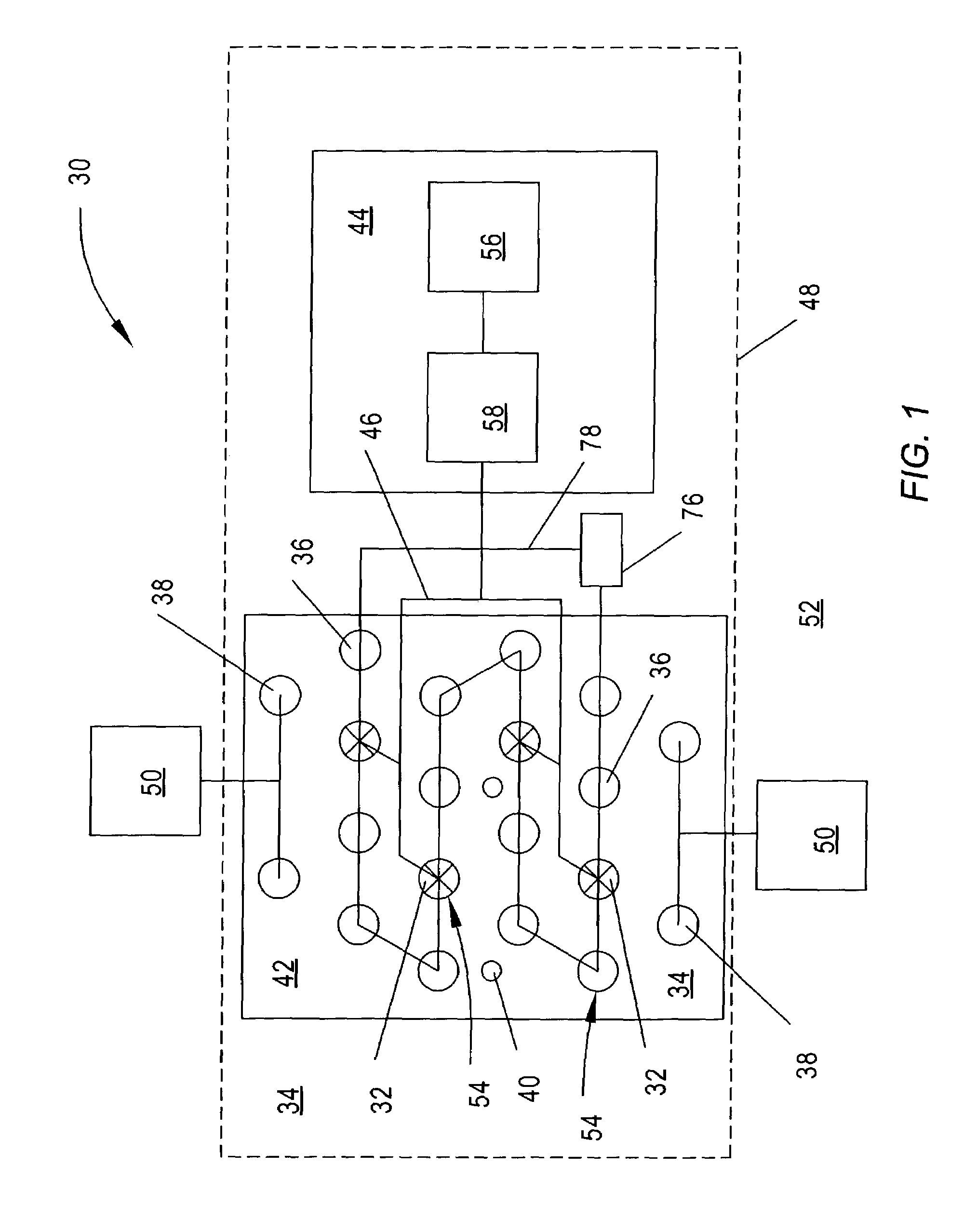
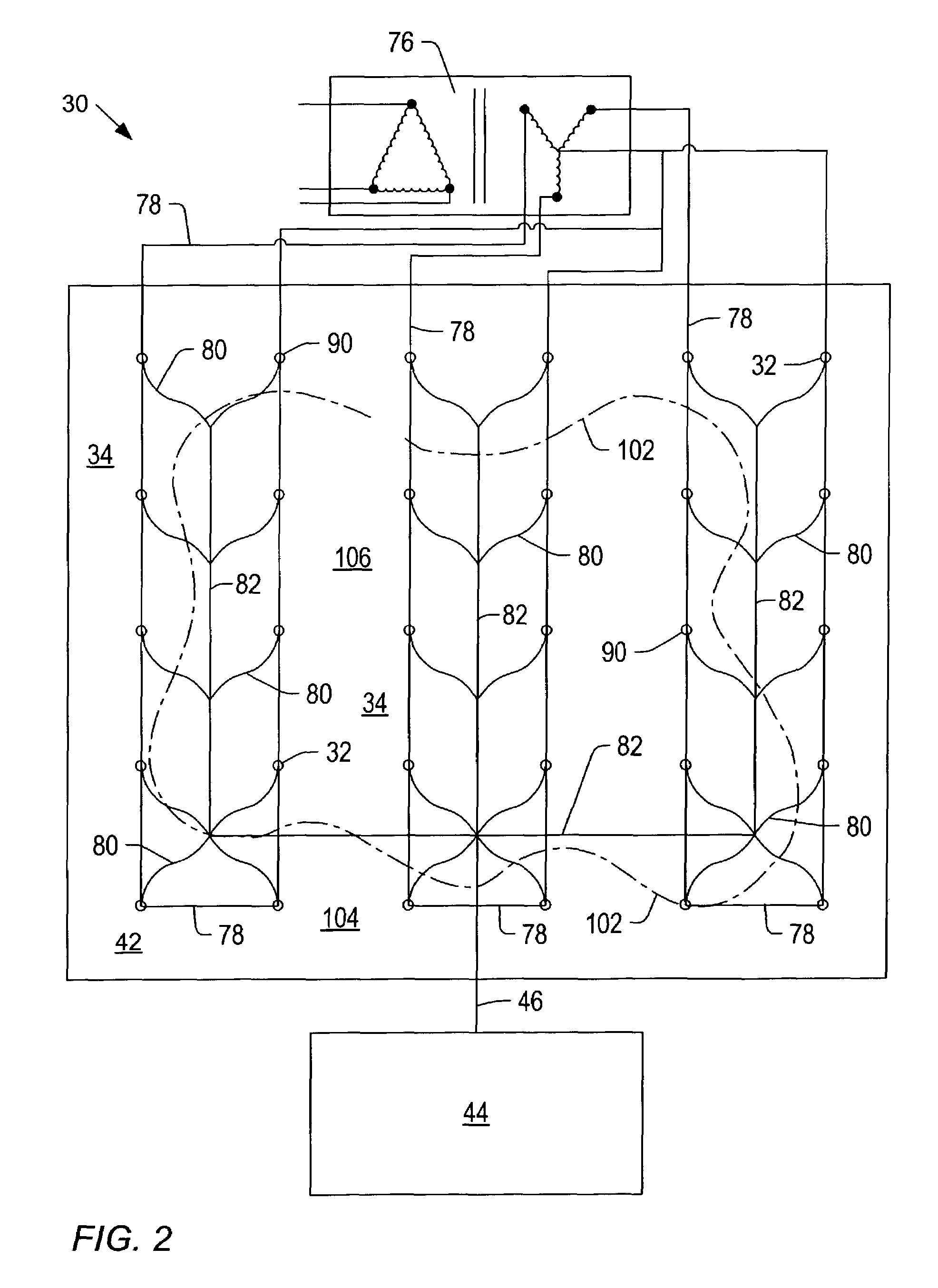
[0054]A soil remediation system may remove or reduce contaminants within a selected soil region. FIGS. 1 and 2 show schematic representations of embodiments of soil remediation systems 30. Soil remediation system 30 depicted in FIG. 1 may include one or more extraction wells 32 within soil 34. Soil remediation system 30 may optionally include one or more heat injection wells 36, one or more fluid injection wells 38, and one or more test wells 40. Fluid injection wells 38 and / or test wells 40 may be located inside or outside of a pattern of extraction wells 32 and heat injection wells 36. Extraction wells 32, heat injection wells 36, fluid injection wells 38, and / or test wells 40 may include well casings. Portions of the well casings may be perforated to allow fluid to pass into or out of the well casings. Alternatively, extraction wells 32, heat injection wells 36, fluid injection wells 38, and / or test wells 40 may include a cased portion and an uncased portion. The uncased portion ...


PUM

PropertyMeasurementUnit
depthaaaaaaaaaa
temperaturesaaaaaaaaaa

Abstract

Methods are provided for remediating contaminated soil. The methods may include collecting contaminated soil at a plurality of treatment sites. The contaminated soil at one or more of the plurality of treatment sites may be at least partially contained. Vapors produced from heating soil at one site may be used to heat contaminated soil at another site. A fluid directed to a portion of heated contaminated soil may accelerate heat transfer through the site of contaminated soil or through another site of contaminated soil. A method may include heating contaminated soil from more than one site at substantially the same time. Heating contaminated soil from more than one site at substantially the same time may include in situ and ex situ treatment at a common location.

Description

BACKGROUND[0001]1. Field of the Invention[0002]The present invention generally relates to soil remediation systems and methods. Embodiments of the invention relate to systems and methods of heating contaminated soil at one or more treatment sites.[0003]2. Description of Related Art[0004]Soil contamination is a matter of concern in many locations. “Soil” refers to unconsolidated and consolidated material in the ground. Soil may include natural formation material such as dirt, sand, and rock, as well as fill material. Soil may be contaminated with chemical, biological, and / or radioactive compounds. Contamination of soil may occur in a variety of ways, such as material spillage, leakage from storage vessels, and landfill seepage. Public health concerns may arise if contaminants migrate into aquifers or into air. Soil contaminants may also migrate into the food supply through bioaccumulation in various species in a food chain.[0005]There are many ways to remediate contaminated soil. “Re...

Claims


Application Information

Patent Timeline
Patent Type & Authority Patents(United States)
IPC IPC(8): A62D3/00B09C1/00B09C1/02B09C1/06B09C1/08B09C1/10
CPCB09C1/00B09C1/005B09C1/02B09C1/06B09C1/08B09C1/10
Inventor STEGEMEIER, GEORGE L.VINEGAR, HAROLD J.
Owner BOARD OF RGT THE UNIV OF TEXAS SYST
Why Eureka
Try Eureka