Vehicle wheel driving apparatus arranging structure

a technology of driving apparatus and driving wheel, which is applied in the direction of electric propulsion mounting, electric devices, electric propulsion mounting, etc., can solve the problems that the driving apparatus for practical use was not practical, and achieve the effects of increasing the ride feel and steering stability, and reducing the longitudinal oscillation of the road wheel

Inactive Publication Date: 2009-05-26
HONDA MOTOR CO LTD
View PDF16 Cites 38 Cited by
  • Summary
  • Abstract
  • Description
  • Claims
  • Application Information

AI Technical Summary

Benefits of technology

[0013]In addition, in consideration of the fact that unsprung load is increased by placing the motor in the wheel or realizing an in-wheel motor, another problem that the invention is to solve is to provide a vehicle wheel driving apparatus arranging structure which can reduce effectively the unsprung longitudinal oscillation of the wheel.
[0031]According to the first aspect of the invention, since the center of gravity of the motor is disposed higher than the center of the road wheel, the unsprung longitudinal oscillation of the road wheel can be reduced which is produced by an input from the road surface when the road wheel runs over irregularities on the road surface or driving force from the motor. In addition, since the plurality of support joints which make up the suspension are disposed to support the road wheel supporting member and at least one of these support joints is disposed higher than the center of the road wheel and is then connected to the motor housing of the motor, the unsprung longitudinal oscillation of the road wheel can be reduced further effectively. As a result, there is provided an advantage that the increase in ride feel and steering stability can be realized.
[0032]According to the second aspect of the invention, since the support joint disposed higher than the center of the road wheel is positioned above or in the vicinity of the rotational shaft of the motor, there are provided advantages that the vicinity of the center of gravity of the motor can be supported and that the unsprung longitudinal oscillation of the road wheel can be reduced effectively.
[0033]According to the third aspect of the invention, since the support joint disposed higher than the center of the road wheel is mounted on the motor housing via the bracket or directly, there is provided an advantage that the versatility in mounting the support joint can be increased.
[0034]According to the fourth aspect of the invention, since the support joint is made to constitute the end of the arm disposed in the longitudinal direction of the vehicle body in the inclined fashion or the arm made hold the road wheel relative to the displacement of the longitudinal direction of the vehicle body or the end of the suspension constituent member, the unsprung longitudinal oscillation of the road wheel can be reduced effectively, whereby there is provided an advantage that the increase in ride feel and steering stability can be realized.
[0035]According to the fifth aspect of the invention, since at least one of the plurality of support joints is disposed lower than the center of the road wheel and the support joint so disposed is made to constitute the end of the arm disposed in the longitudinal direction of the vehicle body in the inclined fashion or the arm made to hold the road wheel relative to the displacement in the longitudinal direction of the vehicle body or the end of the suspension constituent member, a synergetic effect between the support shaft and the support shaft which is disposed higher than the center of the road wheel can be expected. As a result, there is provided an advantage that the unsprung longitudinal oscillation of the road wheel can desirably reduced further.

Problems solved by technology

Consequently, vehicle wheel driving apparatus for practical use were not always such that an axle of a road wheel and a rotational shaft of a motor was caused to coincide with each other.

Method used


Image

  • Vehicle wheel driving apparatus arranging structure
  • Vehicle wheel driving apparatus arranging structure
  • Vehicle wheel driving apparatus arranging structure

Examples


Embodiment Construction

[0045]Embodiment of the invention will be described below based on the accompanying drawings. Note that the drawings are to be seen in a direction in which the orientation of reference numerals becomes proper.

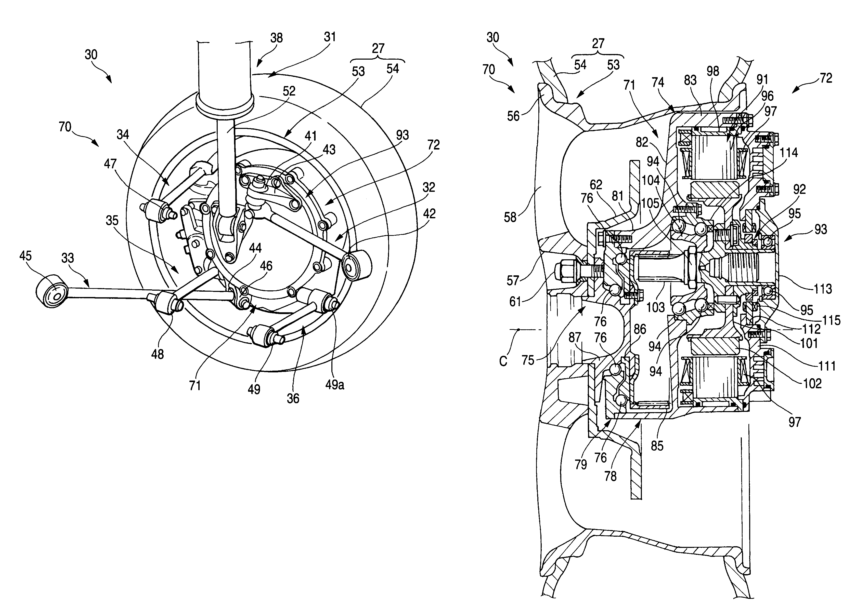
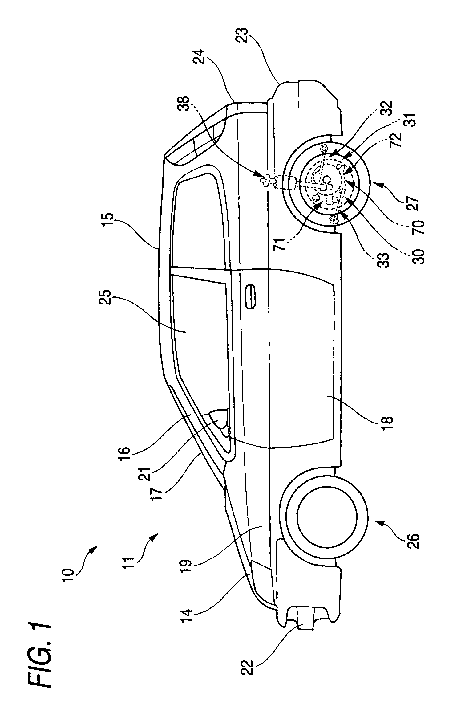
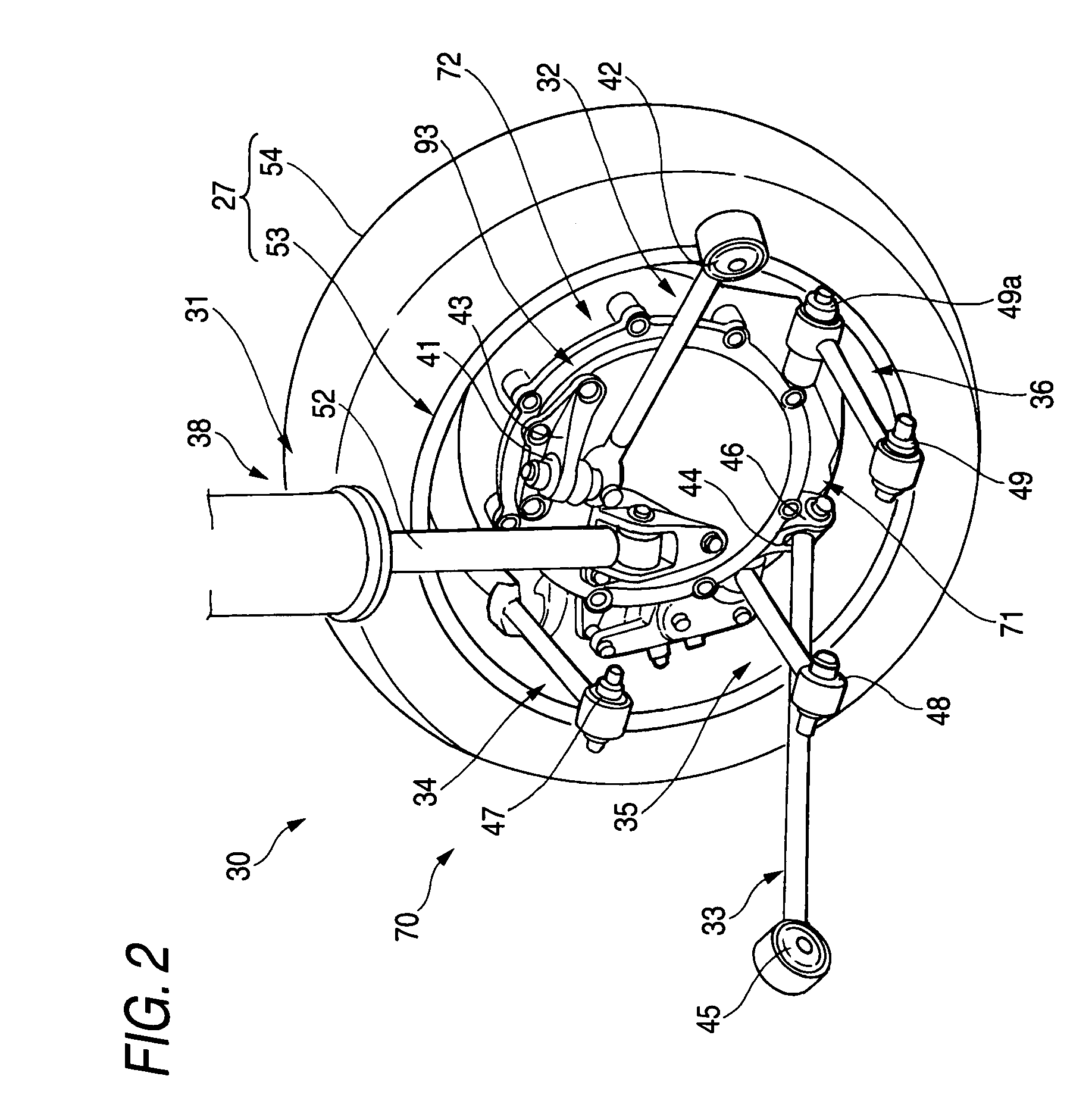
[0046]FIG. 1 is a side view of a vehicle which adopts a vehicle wheel driving apparatus arranging structure according to the invention, and in the figure, reference numeral 10 denotes a vehicle, 11 a vehicle body, 14 a bonnet or engine compartment hood, 15 a roof, 16 a front pillar, 17 a front side window, 18 a door, 19 a front fender, 21 an outside rearview mirror, 22 a front bumper, 23 a rear bumper, 24 a tailgate, 25 a passenger compartment, 26 a wheel, 27 a rear road wheel as a road wheel, and 31 a suspension.

[0047]The vehicle 10 is a fuel cell vehicle in which a fuel gas such as hydrogen is brought into chemical reaction within a fuel cell (not shown) to thereby generate electric current so as to supply electric current so generated to a motor (an electric motor) 72 for dr...


PUM


Abstract

A vehicle wheel driving apparatus arranging structure has a road wheel 27, a road wheel supporting member 71 connected to a vehicle body via a suspension 31 to support the road wheel 27, and a motor 72 rotating a road wheel side of the road wheel supporting member 71. A center of gravity of the motor 72 is disposed higher than a center C of the road wheel 27, a plurality of arms 32 to 36 which make up the suspension 31 are disposed to support the road wheel supporting member 71, at least one of the arms 32 to 36 is disposed higher than the center of the road wheel 27, and one end of the arm 32 which is disposed higher than the center C of the road wheel 27 is connected to a motor housing 93 of the motor 72.

Description

BACKGROUND OF THE INVENTION[0001]1. Field of the Invention[0002]The present invention relates to a vehicle wheel driving apparatus arranging structure in which an axle of a road wheel and a rotational shaft of an in-wheel motor are disposed eccentrically with each other.[0003]2. Description of Related Art[0004]In recent years, on vehicles, techniques for disposing a motor inside a rim of a wheel have been under development in an attempt to simplify a power transmission apparatus from a power source to a wheel and enhance the power transmission efficiency. Since a vehicle wheel driving apparatus (in-wheel motor) like this is such as to drive a wheel which is a high load, an output torque is designed to be increased by reducing the rotational speed of the motor by a gear mechanism.[0005]Consequently, vehicle wheel driving apparatus for practical use were not always such that an axle of a road wheel and a rotational shaft of a motor was caused to coincide with each other.[0006]As a veh...

Claims


Application Information

Patent Timeline
Patent Type & Authority Patents(United States)
IPC IPC(8): B60K1/00
CPCB60G3/20B60G7/008B60K7/0007B60K17/043B60G2200/184B60G2200/422B60G2200/466B60G2204/148B60G2300/50B60K2007/0038B60K2007/0061B60L2220/46
Inventor KAMIYA, TORU
Owner HONDA MOTOR CO LTD
Why Eureka
Try Eureka