Construction machine

a construction machine and cab technology, applied in the direction of roofs, vehicle cleaning, tractors, etc., can solve the problems of oppressive feeling for operators, difficult to find an installation space for a washer tank, and difficult to install a washer tank within an engine room, so as to improve the comfort of driving

Active Publication Date: 2009-05-26
NIHON KENKI CO LTD
View PDF12 Cites 20 Cited by
  • Summary
  • Abstract
  • Description
  • Claims
  • Application Information

AI Technical Summary

Benefits of technology

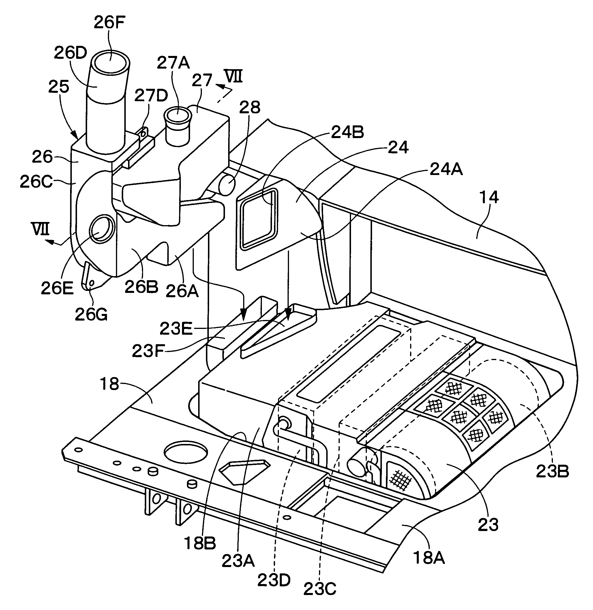
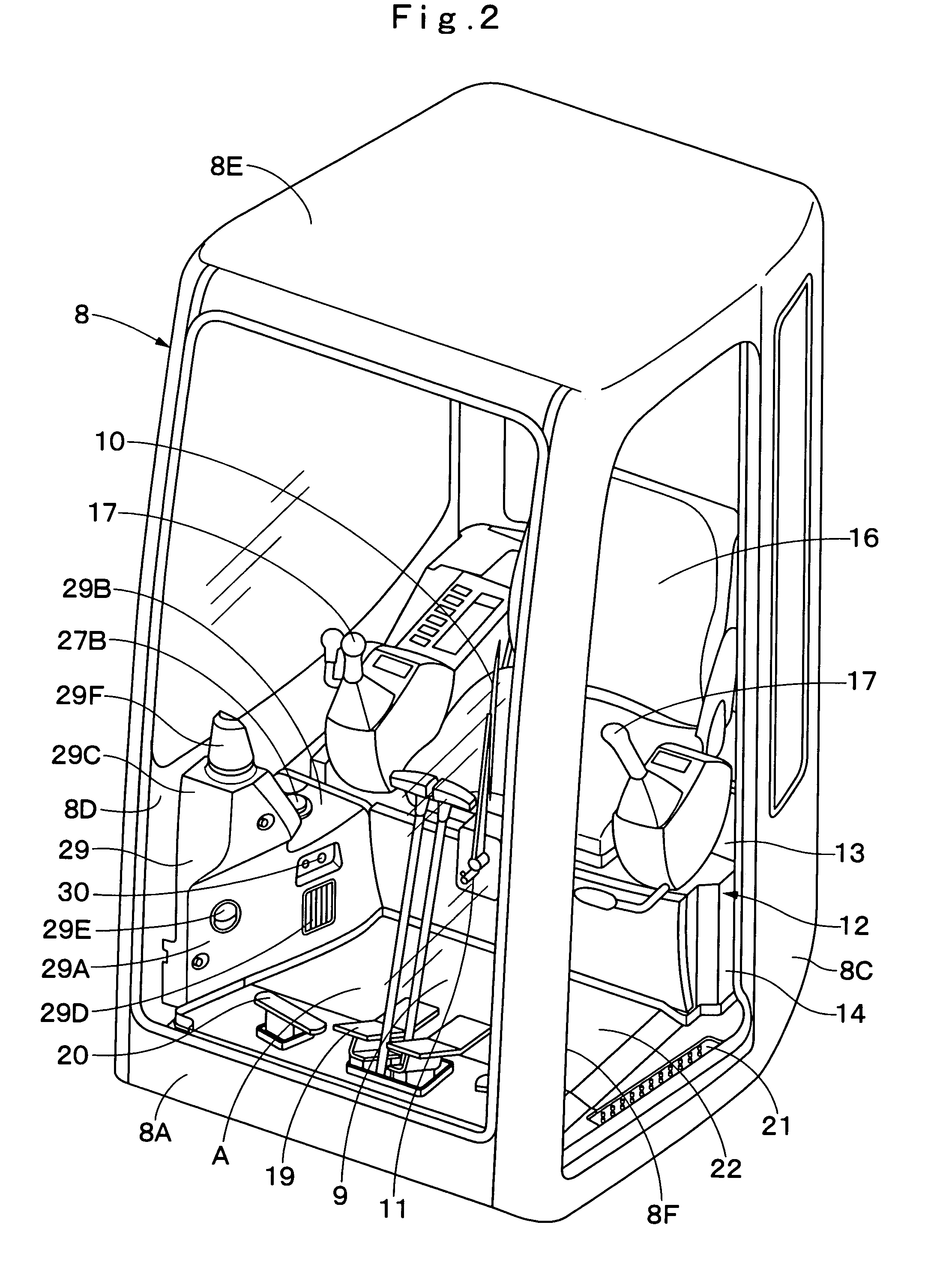
[0006]In view of the above-discussed problems with the prior art, it is an object of the present invention to provide a construction machine having a washer tank installed within a cab in the vicinity of a washer liquid spout nozzle in such a way as to ensure improved comfortableness to drive in and operational reliability as well, without necessitating to provide an installation space exclusively for the washer tank.
[0010]Thus, the washer tank is installed in an unintrusive way, precluding the possibilities of obstructing the view field of an operator by the washer tank or giving an oppressive feeling to an operator by protruding into a dwelling space. Namely, the washer tank is installed in such a way as to ensure comfortableness and working efficiency within the cab. Besides, installation of the washer tank within the cab means that it can be located near the washer liquid spout nozzle, and connected to the latter by the use of a short hose which is less susceptible to damages, that is to say, which has higher operational reliability. The integration of the washer tank with the air duct has another advantage that, in case of operations in a cold district, the washer liquid in the washer tank can be heated by warm air streams in the air duct, that is to say, which precludes the possibilities of freezing the washer liquid.
[0018]With the arrangements just described, the air duct and the washer tank are covered with a decorative duct cover to improve the appearance of the duct-tank assembly. In addition, a filling inlet port of the washer tank is projected upward through the duct cover, allowing to refill a washer liquid into the washer tank easily through the projected filling inlet port.
[0020]With the arrangements just described, the air duct and the washer tank are covered with a decorative duct cover to improve the appearance of the duct-tank assembly. In addition, through a check-out window which is provided in the duct cover, an operator can check out the level of residual washer liquid in the washer tank to complete an initial check-out of a starting procedure in an efficient manner.
[0022]With the arrangements just described, the air duct and the washer tank can be installed at once, making an assembling work simple and efficient. Besides, the front air duct and the washer tank can be fablicated at a low cost.

Problems solved by technology

However, in the case of small-size hydraulic excavator with a limited accommodation space within a cab, it is difficult to find an installation space for a washer tank.
Therefore, if a washer tank is installed within a cab, it could obstruct the view field of an operator or stick out into the dwelling space to such a degree as to give an oppressive feeling to the operator.
Further, in the case of small-size hydraulic excavator, it is difficult to install a washer tank within an engine room as in above-mentioned Japanese Patent Laid-Open No. 2002-13161 because usually an engine room is crowded with engine and hydraulic equipments.
Even if one has succeeded in installing a washer tank within an engine room, it becomes necessary to connect the washer tank with a nozzle by the use of a long hose, which has greater possibilities of being crushed or damaged en route to the hose, making it difficult to give an assurance in performance quality.

Method used


Image

  • Construction machine
  • Construction machine
  • Construction machine

Examples


Embodiment Construction

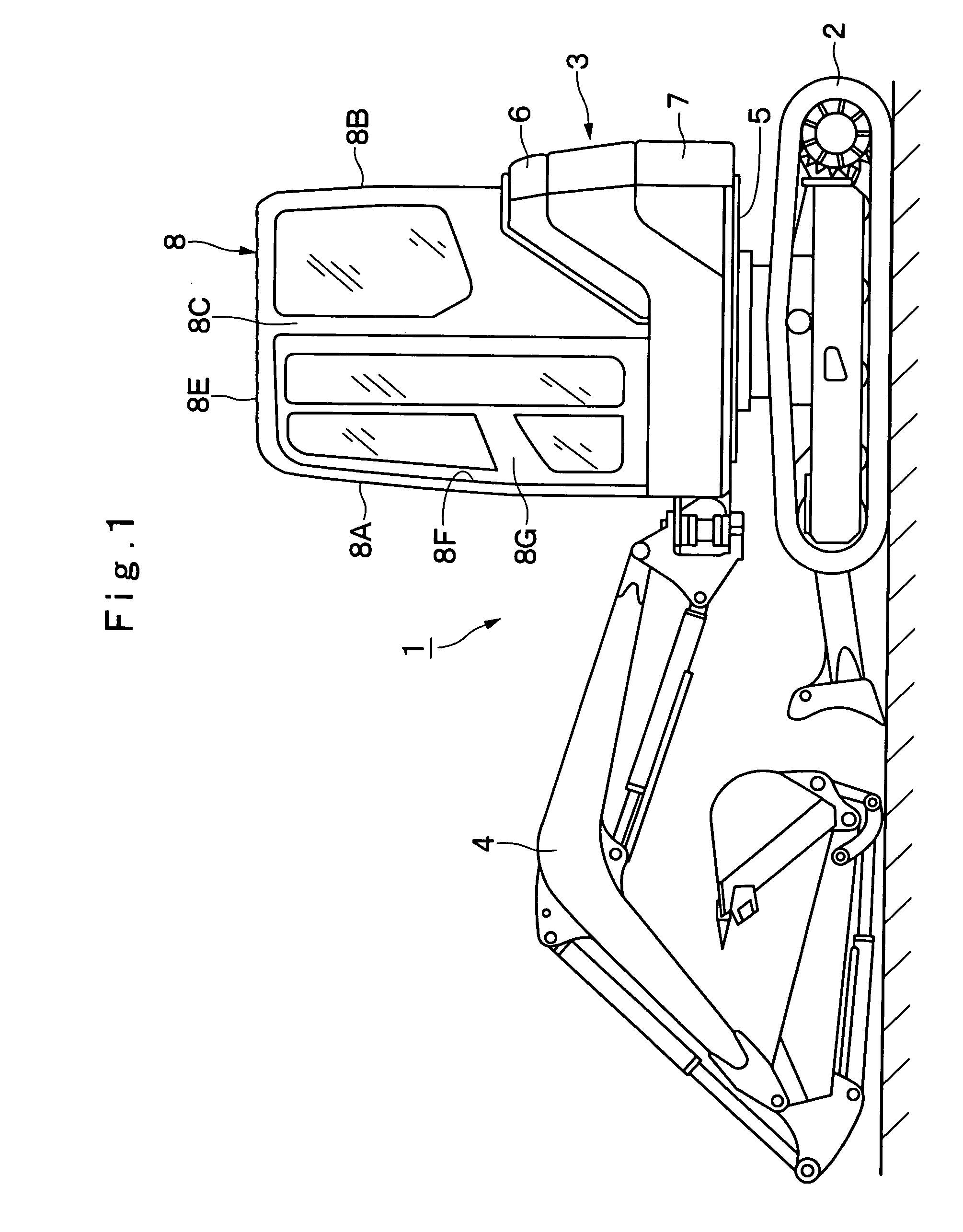
[0035]Hereafter, with reference to FIGS. 1 through 8, the present invention is described more particularly by way of its preferred embodiments which are applied by way of example to an automotive hydraulic excavator, which is considered as a construction machine.

[0036]In FIG. 1, indicated at 1 is a cab-equipped automotive hydraulic excavator typical of construction machines to which the present invention is applicable. The hydraulic excavator 1 is largely constituted by an automotive vehicular lower structure 2, an upper revolving structure 3 which is swingably mounted on the vehicular lower structure 2, forming a vehicle body together with the lower structure 2, and a working mechanism 4 which is liftably mounted in a front side of the upper revolving structure 3 to perform a ground excavating operation or other jobs.

[0037]In this instance, the upper revolving structure 3 is largely constituted by a revolving frame 5 which is formed, for example, by the use of thick steel plates, a...


PUM


Abstract

A washer tank is integrally formed with a front air duct, and the washer tank and the front air duct are installed within a cab. Thus, the washer tank can be installed within the cab by the use of spaces around the air duct. This arrangement makes it possible to install the washer tank within the cab in an unintrusive way and in the vicinity of a washer liquid spout nozzle without necessitating to provide an installation space exclusively for the washer tank.

Description

TECHNICAL FIELD[0001]This invention relates to a cab-equipped construction machine such as a hydraulic excavator, hydraulic crane, wheel loader or the like.BACKGROUND ART[0002]Generally, hydraulic excavators are well known as a construction machine. Hydraulic excavators of this sort are largely constituted by an automotive vehicular lower structure, an upper revolving structure rotatably mounted on the vehicular lower structure, and a working mechanism liftably provided in a front side of the upper revolving structure. A cab is built on a revolving frame of the upper revolving structure, and an operator's seat is provided within the cab to be taken by an operator. On certain cab-equipped hydraulic excavator, an air-conditioning unit is installed to send conditioned air into a cab through an air duct for providing an improved working environment.[0003]Further, along with a wiper which is provided on a front window pane of a cab for wiping water droplets from the front window pane, a ...

Claims


Application Information

Patent Timeline
Patent Type & Authority Patents(United States)
IPC IPC(8): B62D33/06B60H1/00E02F9/16B60S1/50B62D25/08B62D33/063E02F9/08
CPCB60H1/00378B60H1/00564B60S1/50B62D33/0617B62D33/0633E02F9/0883E02F9/16B60H1/243B62D25/08
Inventor ISHII, HAJIMETANAKA, TOMOYUKIKIMURA, SHOGO
Owner NIHON KENKI CO LTD
Why Eureka
Try Eureka