Electromagnetic relay

a technology of electromagnetic relays and relays, applied in electromagnetic relays, electrical apparatus, electromagnetical relay details, etc., can solve the problems of easy hermeticity, operational failure, contact failure of contact portions, etc., and achieve high air permeability and water resistance, high water resistance, and shape and dimension control

Active Publication Date: 2009-05-26
EM DEVICES CORP
View PDF8 Cites 16 Cited by
  • Summary
  • Abstract
  • Description
  • Claims
  • Application Information

AI Technical Summary

Benefits of technology

[0011]In view of the above, it is an object of the present invention to provide an electromagnetic relay which is capable of preventing an operational failure and a contacting failure at contact portions by maintaining air permeability and resistance to water (water invasion preventing property) even after being heated at a high temperature and by avoiding invasion of a coating agent. That is, the object of the present invention is to provide the electromagnetic relay which enables application of the coating agent even after being mounted on printed circuit boards having undergone reflow heating and water cleaning without causing an increase in component counts while maintaining air permeability and preventing the invasion of water.
[0013]a main body including an electrical contact portion, an electromagnetic driving portion, and a molded resin base for mounting the electrical contact portion and the electromagnetic driving portion; wherein the main body is covered with a molded resin cover and is sealed with a sealing resin and wherein one or more through-holes are formed by applying laser beam to desired positions of the molded resin cover from an inner surface side thereof so that the through-holes each are within a size range in which no invasion of water from the outer side into the inner side thereof occurs and in which air permeability of the molded resin cover can be maintained through the through-holes.
[0016]a main body including an electrical contact portion, an electromagnetic driving portion, and a molded resin base for mounting the electrical contact portion and the electromagnetic driving portion; wherein the main body is covered with a molded resin cover and is sealed with a sealing resin and wherein one or more through-holes are formed by applying laser beam to desired positions of the molded resin base from an inner surface side thereof, the desired positions which are not covered with the sealing resin on an outer surface side thereof so that the through-holes each are within a size range in which no invasion of water from the outer side into the inner side thereof occurs and in which air permeability of the molded resin base can be maintained through the through-holes.
[0019]a main body including an electrical contact portion, an electromagnetic driving portion, and a molded resin base for mounting the electrical contact portion and the electromagnetic driving portion; wherein the main body is covered with a molded resin cover and is sealed with a sealing resin and wherein the molded resin cover comprises a liquid crystal polymer having skin layers with identical orientation formed on both sides of a core layer in an intermediate position between the skin layers and wherein laser beams are applied to desired positions of the molded resin cover from both inner and outer sides thereof so that the laser beam passes through only the skin layers with the core layer being left unprocessed by the laser beams to form one or more through-holes on each of the skin layers which each are within a size range in which no invasion of water from the outer side into the inner side thereof occurs and in which air permeability of the molded resin cover can be maintained through the through-holes.
[0022]a main body including an electrical contact portion, an electromagnetic driving portion, and a molded resin base for mounting the electrical contact portion and the electromagnetic driving portion; wherein the main body is covered with a molded resin cover and is sealed with a sealing resin and wherein the molded resin cover comprises a liquid crystal polymer having skin layers with identical orientation formed on both sides of a core layer in an intermediate position between the skin layers and wherein laser beams are applied to desired positions of the molded resin base from both inner and outer sides thereof, the desired positions which are not covered with the sealing resin on an outer surface side thereof, so that the laser beams pass through only the skin layers with the core layer being left unprocessed by the laser beams to form one or more through-holes on each of the skin layers which each are within a size range in which no invasion of water from the outer side into the inner side thereof occurs and in which air permeability of the molded resin base can be maintained through the through-holes.
[0024]With the above configuration, it is made possible to provide the electromagnetic relay having both air permeability and resistance to water, which enables the coating process with the coating agent even after being mounted on the printed circuit board having undergone reflow heating and also which enables a water-cleaning process, thereby eliminating an operational failure and contacting failure at contact portions. That is, the electromagnetic relay of the present invention has a method of forming stable air ventilating openings (air holes) on the molded resin even after being heated at high temperature, which ensures only high air permeability and resistance to water (water invasion preventing property) of the electromagnetic relay. The size of each of the air ventilating openings is fine and its shape and dimension can be fully controlled and, as a result, it is possible to achieve high resistance to water while controlling air permeability. Additionally, it is made possible to avoid invasion of the coating agent, thereby preventing the operational failure and contacting failure at contact portions.

Problems solved by technology

In the case where the electromagnetic relay is fully hermetically sealed from the outside, an escape path for air formed inside the relay is shut and, therefore, hermeticity occurs readily due to a thermal stress caused by reflow heating especially at an interface between a metal and a resin each having a different thermal expansion coefficient or in a bonding portion between a molded resin and a sealing resin.
In the electromagnetic relay in which hermeticity has occurred, water, solvent, or a like invade from the outside, which causes an operational failure and a contacting failure of contact portions.
However, in the case of the through-holes 2 formed on the top of the molded resin cover 1, since conditions for shapes and diameters are to be satisfied by considering moldability and workability of thermal caulking and since its aperture portion is wide, there is a risk that all kinds of substances on an outside of the electromagnetic relay invade easily into the electromagnetic relay.
If the through-holes 2 are shut by the coating agent, the coating agent invades inside of the electromagnetic relay in some cases, causes an operational failure and / or contacting failure at contact portions.
Thus, the unsealed through-holes 2 (2a) which do not provide a sealed state have a remarkably high risk and a limitation is imposed on the execution of unsealing method.
The above-disclosed technology to increase heat-resistance and / or bonding characteristic of the sealing resin 5 are not sufficient to provide methods of improving bonding strength that can satisfy all conditions for diverse reflow heating.
There is a limit point at which pressure inside the electromagnetic relay becomes high due to a high temperature and hermeticity failure occurs due to excessive thermal expansion.
Moreover, the sealing resin 5 is vulnerable to changes by a coating condition, thermosetting condition, circumferential conditions such as an ambient temperature, humidity or the like and, therefore, its bonding characteristic is easy to change and it is impossible to keep its bonding strength constant in the manufacturing processes.
As a result, the limit point causing the hermeticity failure changes.
Each of the technology to apply porous filters (the Patent Reference 1) and the technology to apply polymerized monomers to form air holes has problems (Patent Reference 2) in that it is difficult to establish the method of the applications.
Moreover, the heat stress in the reflow heating causes it difficult to keep the air holes constantly porous.
Additionally, new problems of an increase of component counts, increased costs caused by the increase of component counts, and increased number of man-hours arise.

Method used


Image

  • Electromagnetic relay
  • Electromagnetic relay
  • Electromagnetic relay

Examples


first embodiment

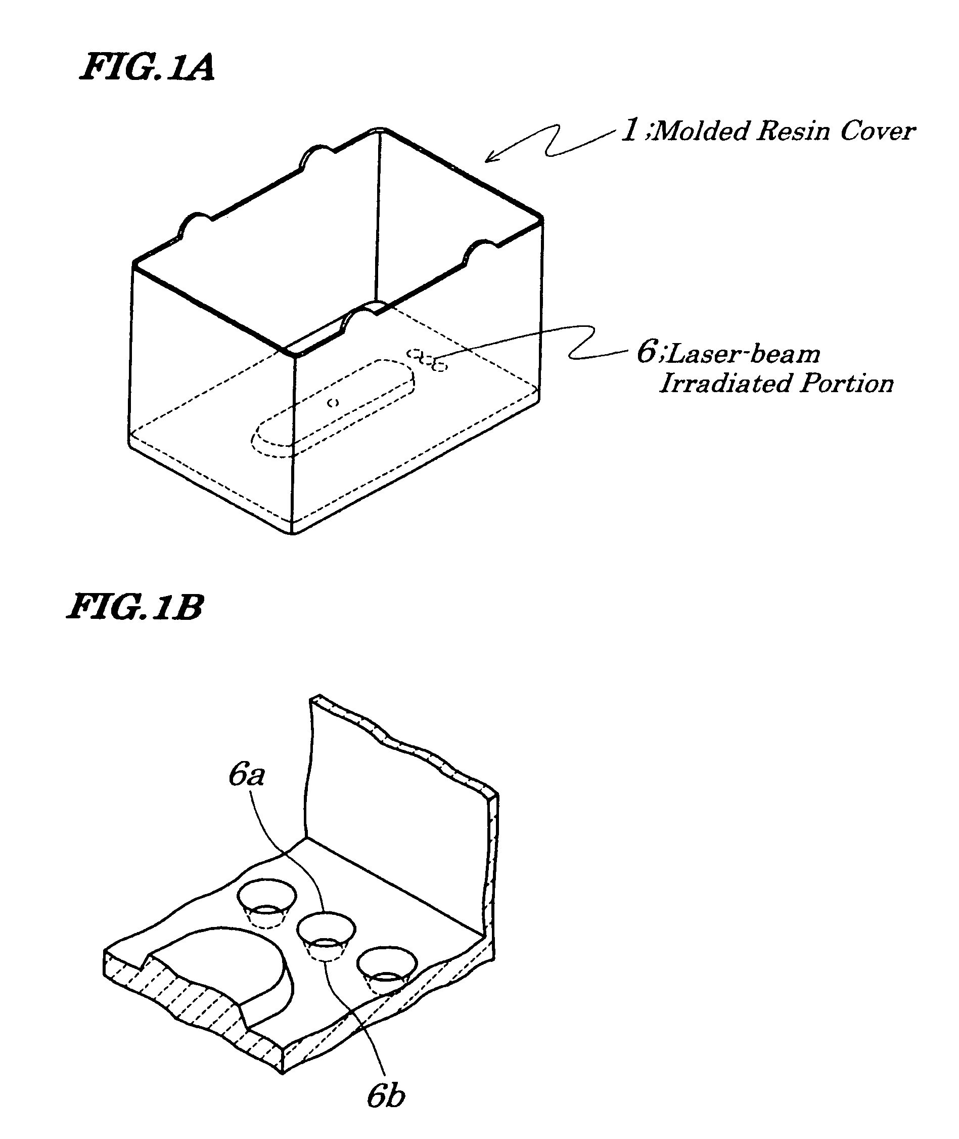
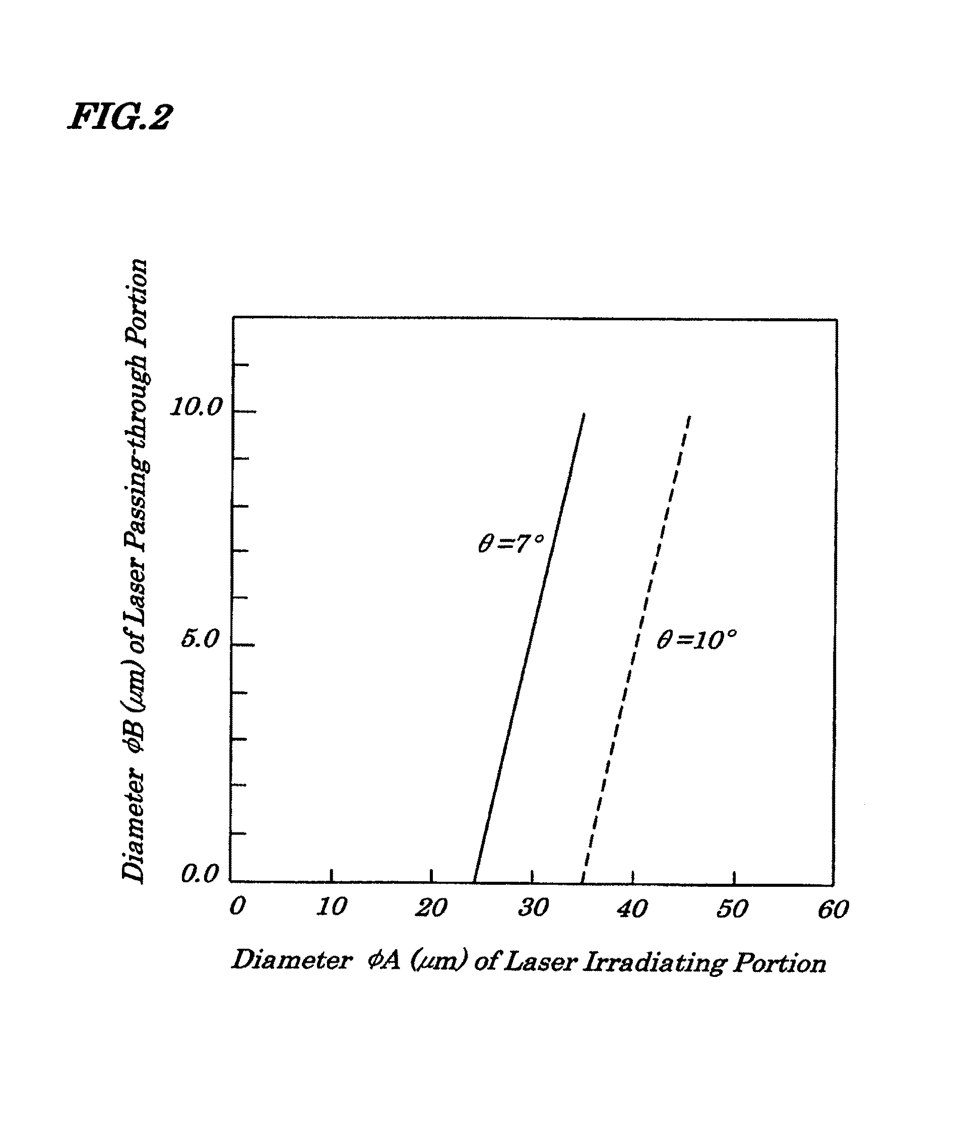
[0035]FIGS. 1A and 1B are diagrams showing an electromagnetic relay according to a first embodiment of the present invention and FIG. 1A is a perspective view of a molded resin cover 1 with its aperture portion faced upward and FIG. 1B is an expanded diagram showing portions 6 (6a, 6b) where laser-beam irradiation was performed. In the first embodiment, laser beam is applied surely from an inside of the molded resin cover 1, that is, from a face being opposite to a main body of the electromagnetic relay. Such a technology of applying laser beam is provided by, for example, Shinozaki Manufacturing Co., Ltd (Japan). In an example of forming a shape like this, a relation of a diameter φA of the laser-beam irradiated portion 6a and a diameter φB of the laser-beam irradiated portion 6b is shown by an equation φA−2 tanφ·t=φB. FIG. 5 is a cross-sectional view showing a relation between the diameter φA of the laser beam irradiated portion (laser beam coming-in side) and the diameter φB of t...

second embodiment

[0039]FIGS. 3A and 3B are diagrams illustrating an electromagnetic relay according to a second embodiment of the present invention; and FIG. 3A is a perspective view of a molded resin base 4 on which a main body of the electromagnetic relay is mounted and of portions 7 in which laser beam was applied and FIG. 3B is an expanded perspective view of portions 7 in which laser beam was applied. In the first embodiment, laser beam is applied surely from an inside of a molded resin cover 1. Instead the configuration of the first embodiment, in the second embodiment, one or more through-holes are formed by applying laser beam to desired positions of the molded resin base 4 from an inner surface side thereof, the desired positions which are not covered with a sealing resin 5 on an outer surface side thereof.

[0040]When a plurality of laser-beam irradiated portions 7 (7a, 7b) each having a structure shown in FIG. 3B is to be formed, the laser-beam irradiated portions 7a are provided with pitch...

third embodiment

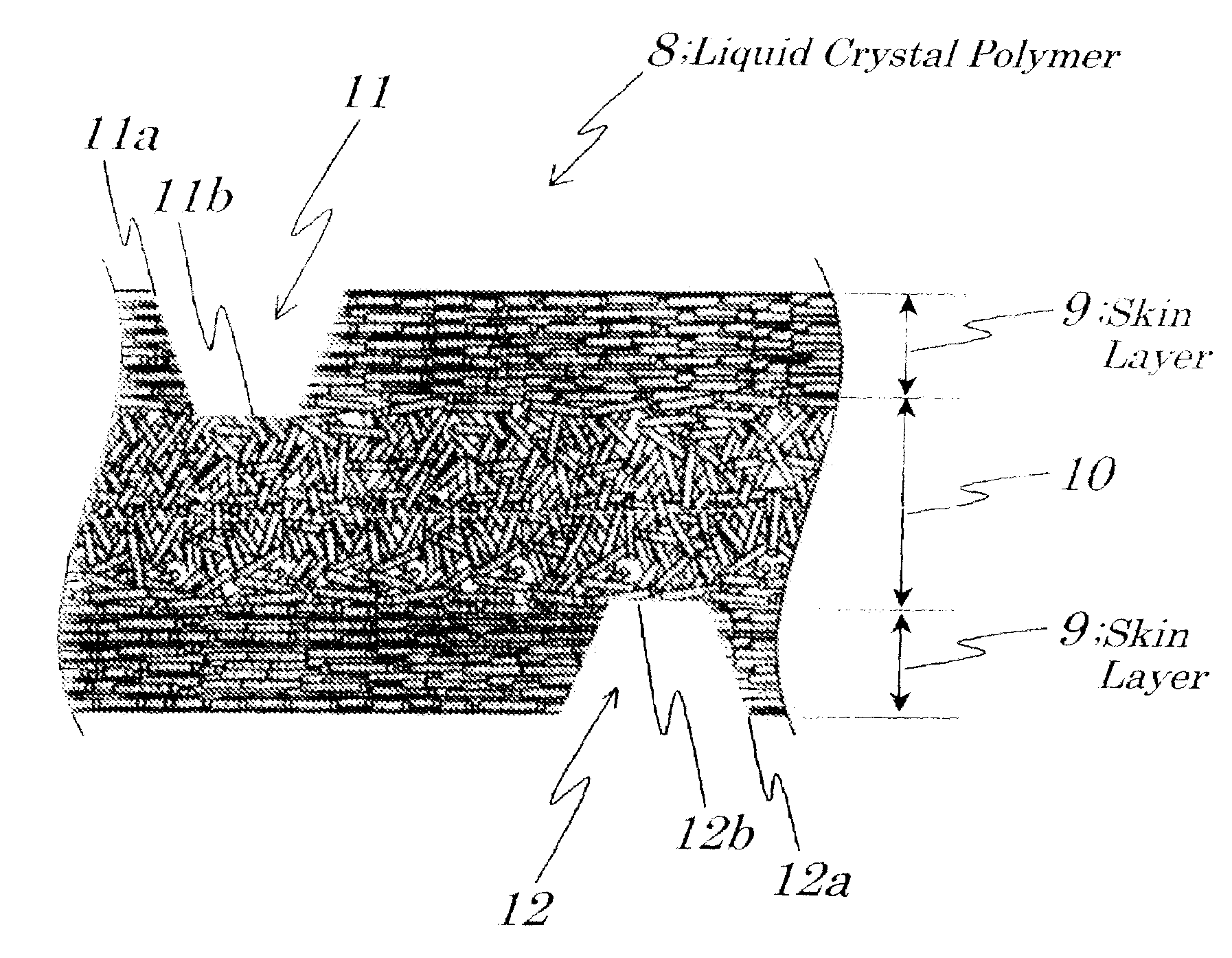
[0043]FIG. 4 is an expanded sectional view of a molded resin cover 1 made of a liquid crystal polymer 8 of the third embodiment which is applied to an electromagnetic relay shown in FIGS. 6A and 6B. It is a characteristic of the liquid crystal polymer 8 that it becomes liquid crystal phase when being in a melted state. As shown in FIG. 4, the molded resin cover 1 is of a three-layered structure including a first skin layer 9 with identical orientation of the liquid crystal formed on a surface side, a second skin layer 9 with identical orientation of the liquid crystal formed on a rear side, and a core layer 10 with random orientation of the liquid crystal formed between the first and second skin layers 9. When air ventilating openings are formed by laser beam irradiation, laser beam is not allowed fully to pass through the liquid crystal polymer 8 and allowed to pass through only the first and second skin layers 9. The first and second skin layers 9 have identical orientation of the...


PUM


Abstract

An electromagnetic relay is provided which enables a coating process with a coating agent even after being mounted on a printed circuit board having undergone reflow heating by preventing invasion of water while maintaining air permeability. A main body making up the electromagnetic relay includes an electrical contact portion, electromagnetic driving portion and molded resin base and is covered with the molded resin cover. One or more through holes are formed by applying laser beam from a rear side of the molded resin cover. A spot diameter of each through hole on a surface of an outside of the molded resin cover is 0.1 μm to 10 μm. Instead of the molded resin cover, through-holes each having a size of 0.1 μm to 10 μm may be formed by applying the laser beam to the molded resin base. Moreover, a liquid crystal polymer may be used as the molded resin cover or base having a filtering function, by forming holes to pass through only skin layers making up the liquid crystal polymer by applying the laser beam to the liquid crystal polymer.

Description

BACKGROUND OF THE INVENTION[0001]1. Field of the Invention[0002]The present invention relates to an electromagnetic relay and more particularly to the electromagnetic relay that can be suitably used as vehicle-mounted electrical components.[0003]2. Description of the Related Art[0004]A conventional electromagnetic relay having a switching function by opening and closing of electrical contacts and being used widely and commonly as a vehicle-mounted component includes electrical contacts and a molded resin material in which a molded resin base and an electromagnetic driving portion formed on the molded resin base are covered with a molded resin cover and is sealed with a thermosetting sealing resin. In the case where the electromagnetic relay is fully hermetically sealed from the outside, an escape path for air formed inside the relay is shut and, therefore, hermeticity occurs readily due to a thermal stress caused by reflow heating especially at an interface between a metal and a res...

Claims


Application Information

Patent Timeline
Patent Type & Authority Patents(United States)
IPC IPC(8): H01H51/22H01H9/04
CPCH01H50/023H01H2229/02
Inventor NISHI, YASUHISAITO, HIROMITSU
Owner EM DEVICES CORP
Why Eureka
Try Eureka