Method and device for optically coupling optical fibres

a technology of optical coupling and optical fiber, which is applied in the field of optical fibers, can solve the problems of power loss, failure of optical amplifier, and relatively difficult performance of manufacturing optical amplifiers and other devices in which optical fibers are optically coupled to each other, and achieves the effects of convenient assembling, efficient transmission of power, and easy optimization of relationships

Inactive Publication Date: 2009-05-26
9180 8030 QUEBEC
View PDF7 Cites 18 Cited by
  • Summary
  • Abstract
  • Description
  • Claims
  • Application Information

AI Technical Summary

Benefits of technology

[0012]Advantageously, the optical coupler allows to relatively easily assemble together the optical coupler and the first and second optical fibers. Furthermore, the optical coupler and optical fibers assembly is relatively robust and relatively efficient in transmitting power between the first optical fiber and the second optical fiber.
[0013]Yet, furthermore, the proposed optical coupler allows to relatively easily optimize relationships between the cross-sectional area over which the light propagating in the first and second optical fibers and the numerical apertures of the first and second optical fibers so as to optimize power transmission between the first optical fiber and the second optical fiber.
[0014]Another advantage of the present optical coupler resides in the possibility to optically couple to many types of optical fiber that are often difficult to couple to conventionally, such as for example monomode fibers, polarisation-maintaining fibers and microstructured fibers, among other possibilities.
[0015]The present invention has also an advantage that it facilitates the coupling of optical fibers that are heat sensitive as the second optical fiber may be glued to the optical coupler. Furthermore, since the first optical fiber may be fused with the optical coupler before inserting the second optical fiber, the second optical fiber can also be heat sensitive and nevertheless be used with the proposed optical coupler according to the invention.

Problems solved by technology

This creates surface tension problems that result in power losses.
Since it is desirable, in many instances, to pump relatively large power into the signal fiber, these power losses may heat the optical fibers and eventually lead to failure of the optical amplifier.
In addition, these methods for manufacturing optical amplifiers and other devices in which optical fibers are optically coupled to each other are relatively difficult to perform and it is relatively difficult to achieve reproducible results using these methods.
Once again, these methods for manufacturing optical fibers are relatively complex to implement.
Also, they may lead to the creation of stresses within the coupled assemblies, as there is typically a need to handle the optical fibers and attach them to supports for packaging purposes.

Method used


Image

  • Method and device for optically coupling optical fibres
  • Method and device for optically coupling optical fibres
  • Method and device for optically coupling optical fibres

Examples


Embodiment Construction

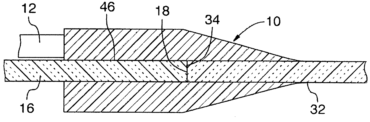
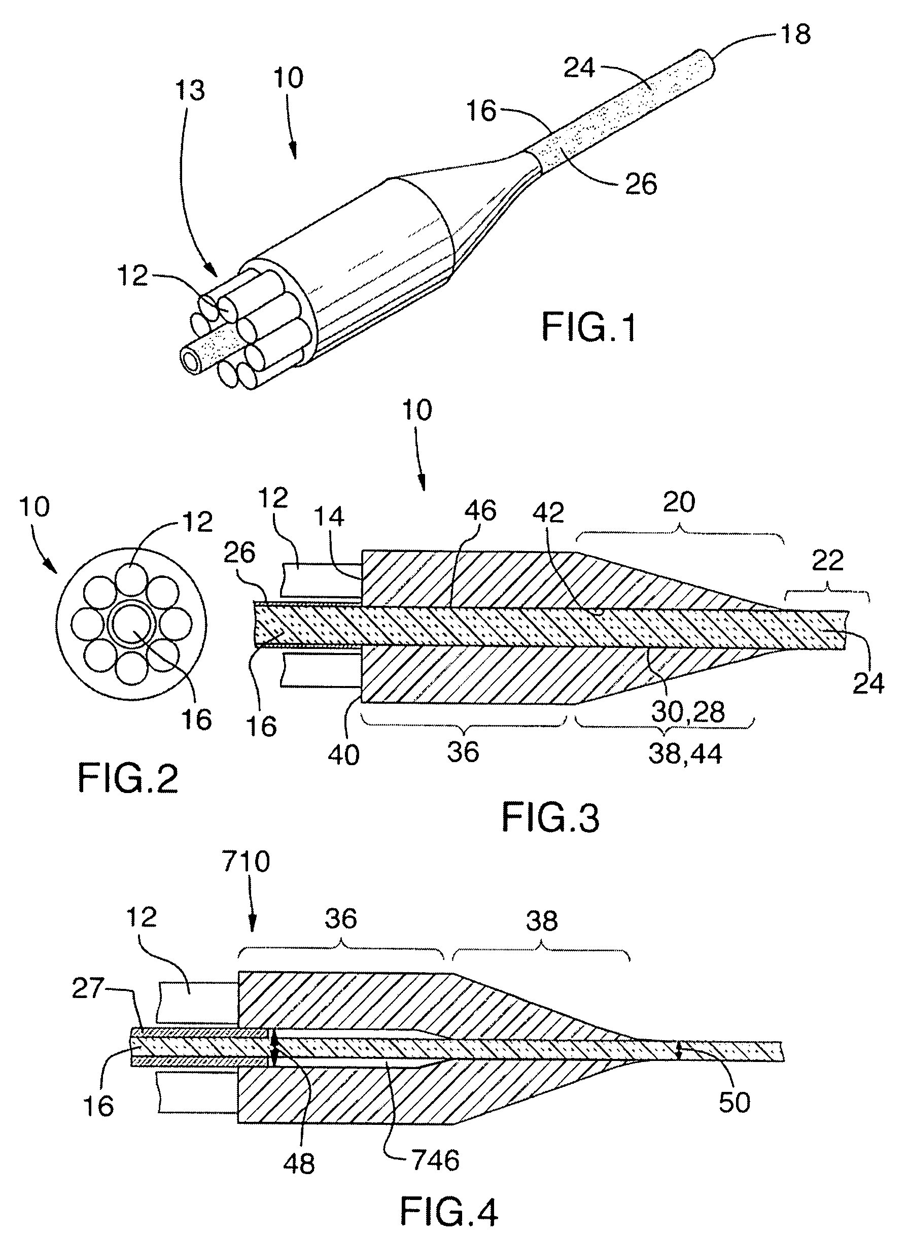
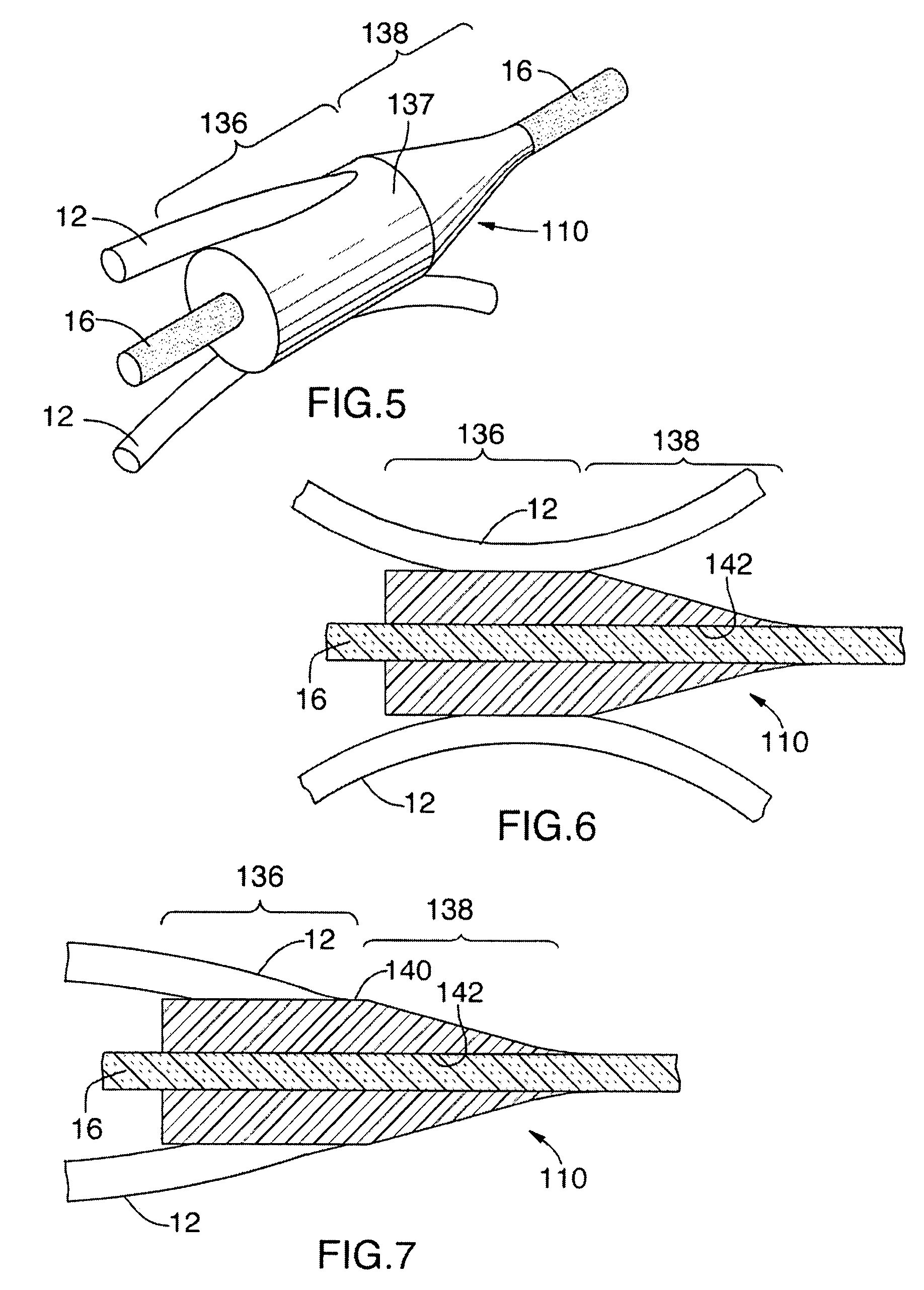
[0047]FIGS. 1 to 3 illustrate an optical coupler 10 in accordance with an embodiment of the present invention. The optical coupler 10 is usable for optically coupling a first optical fiber 12 to a second optical fiber 16. In some embodiments of the invention, as seen in FIGS. 1 to 3, more than one optical fiber 12 are optically coupled to the second optical fiber 16. For example, these other optical fibers take the form of a bundle of optical fibers 13. In summary, the optical coupler 10 is manufacturable such that it includes a surface for coupling to the second optical fiber 16 in a substantially radial direction. The surface is formed so as to have a shape that substantially conforms to the outer surface of the second optical fiber 16.

[0048]The optical coupler 10 is configured and has optical properties such that essentially all the light incoming at the first optical fiber 12 is guided into the second optical fiber 16. Typically, this is achieved by adiabatically tapering the op...


PUM


Abstract

An optical coupler, the optical coupler being usable with a first optical fiber and a second optical fiber. The second optical fiber defines a second fiber coupling section and a second fiber transmitting section extending from the second fiber coupling section. The second fiber coupling section defines a radially outwardmost peripheral surface, the radially outwardmost peripheral surface defining a peripheral surface coupling portion. The optical coupler includes a coupler first end section and a substantially opposed coupler second end section, the coupler first end section defining a first coupling surface. The optical coupler defines a second coupling surface extending along the coupler first and second end sections. The first coupling surface is optically couplable with the first optical fiber and the second coupling surface is positionable so as to extend substantially parallel to the peripheral surface coupling portion and to be optically coupled with the peripheral surface coupling portion. The optical coupler has optical and geometrical properties such that substantially all the light guided to the first coupling surface by the first optical fiber is directed towards the second coupling surface and into the second optical fiber through the peripheral surface coupling portion so as to be guided into the second fiber coupling section for transmission into the second fiber transmitting portion.

Description

[0001]This application claims the benefit of U.S. provisional application No. 60 / 879,817, filed on Jan. 11, 2007, the contents of which is hereby incorporated by reference in its entirety.FIELD OF THE INVENTION[0002]The present invention relates to the general field of optical fibers, and is particularly concerned with methods and devices for optically coupling optical fibers.BACKGROUND OF THE INVENTION[0003]There are many occurrences wherein it is desirable to optically couple two or more optical fibers to each other. For example. In optical amplification, a signal fiber carries a signal and is optically pumped using laser light having another wavelength to amplify the signal. To that effect, the laser light coming from the pump fibers is carried into the signal fiber and thereby provides the power required to amplify the signal circulating in, the signal fiber.[0004]Many techniques are available for optically coupling optical fibers to each other in this manner. For example, in on...

Claims


Application Information

Patent Timeline
Patent Type & Authority Patents(United States)
IPC IPC(8): G02B6/26G02B6/42
CPCG02B6/2804G02B6/02376G02B6/2808G02B6/2817G02B6/2821H01S3/094003H01S3/094053
Inventor GONTHIER, FRANCOIS
Owner 9180 8030 QUEBEC
Why Eureka
Try Eureka