Laser sintered titanium alloy and direct metal fabrication method of making the same

a technology of titanium alloy and laser sintered, which is applied in the direction of additive manufacturing, process efficiency improvement, additive manufacturing apparatus, etc., can solve the problems of inability to effectively bind powdered build material containing titanium or titanium alloys, long and expensive post-casting machining and retooling process, and inability to effectively bind titanium alloy powder

Active Publication Date: 2009-06-02
THE BOEING CO
View PDF36 Cites 16 Cited by
  • Summary
  • Abstract
  • Description
  • Claims
  • Application Information

AI Technical Summary

Problems solved by technology

Casting the block of material is a relatively cost efficient and accurate process, although forming the final part using post-casting machining and retooling processes can be long and expensive.
However, rapid prototyping has typically been used to produce plastic parts, and there are few techniques for successfully manufacturing parts incorporating metals.
Although these binders are effective for binding some metal powders, they are unable to effectively bind powdered build material containing titanium or titanium alloys.
Polymer binders leave a significant carbon residue that causes titanium parts to be brittle, and consequently ineffective.
Also, boron does not have the desired eutectic behavior for enhancing the liquid phase sintering step with titanium alloys.
However, neither method is able to build intricate, discontinuous surfaces such as net shaped structures on the parts.
Also, internal cavities and channels are virtually impossible to form due to lack of support during the building process.

Method used


Image

  • Laser sintered titanium alloy and direct metal fabrication method of making the same
  • Laser sintered titanium alloy and direct metal fabrication method of making the same

Examples


Embodiment Construction

[0013]The following detailed description is merely exemplary in nature and is not intended to limit the invention or the application and uses of the disclosure. Furthermore, there is no intention to be bound by any expressed or implied theory presented in the preceding technical field, background, brief summary or the following detailed description.

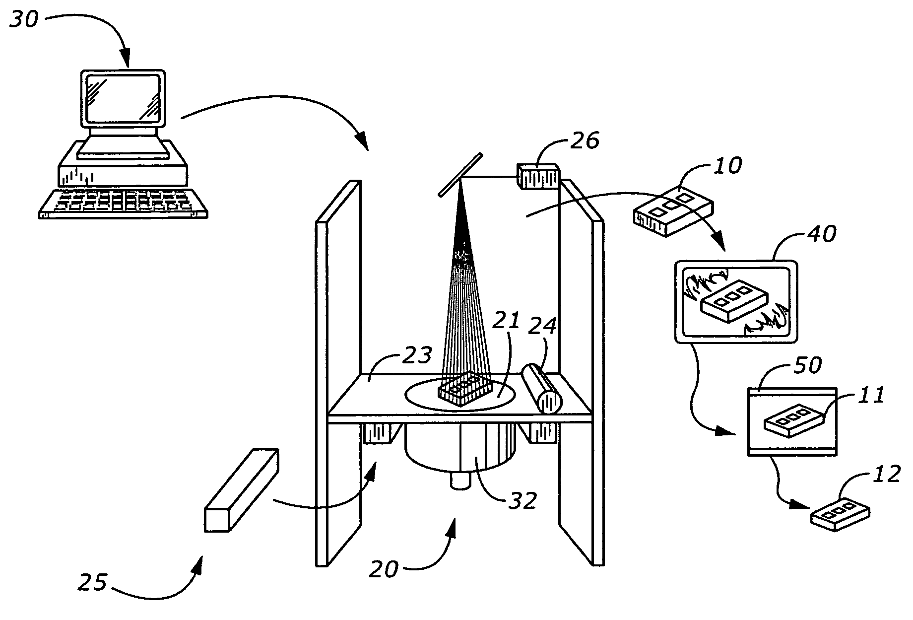
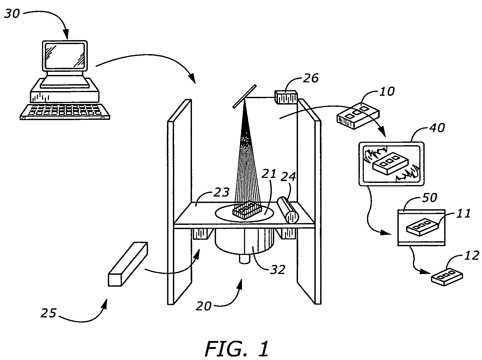
[0014]The present disclosure includes a DMF method for forming parts made from titanium or titanium alloys. The DMF process illustrated in FIG. 1 uses an SLS apparatus 20 to fabricate a preform part, hereinafter referred to as a green part 10. The SLS machine 20 includes a working surface 23 that includes a platform 21 on which a green part is formed layer-by-layer from a metal powder 25. The platform 21 may be constructed to descend into a cavity 22 as incremental layers of powder 25 are applied onto previously formed layers. The individual powder layers may be applied using a roller 24 or other known means for applying a uniform powder ...


PUM

PropertyMeasurementUnit
temperatureaaaaaaaaaa
thicknessaaaaaaaaaa
thicknessaaaaaaaaaa

Abstract

Methods and powder blends are provided for fabricating a metal part. One method includes the first steps of spreading a layer of a powder blend on a platform, the powder blend including a titanium base metal or alloy, and an alloying metal having a lower melting temperature than that of the base metal or alloy. Next, an energy beam is directed onto selected areas of the powder blend layer to thereby melt the alloying metal. Then, the alloying metal is re-solidified by withdrawing the energy beam from the powder blend layer. Then, a preform part is built up by iteratively performing the spreading, melting, and re-solidifying steps on additional adjacently formed layers. A metal liquid phase sintering process is performed at a temperature sufficient to melt the alloying metal but not the base metal or alloy.

Description

TECHNICAL FIELD[0001]The present disclosure generally relates to titanium alloys and methods of making the same, and more particularly relates to the direct fabrication of parts from titanium alloys.BACKGROUND[0002]Three-dimensional parts are typically machined using a molded block of material as a starting point. Casting the block of material is a relatively cost efficient and accurate process, although forming the final part using post-casting machining and retooling processes can be long and expensive.[0003]A more sophisticated method for manufacturing parts is commonly called rapid prototyping. Rapid prototyping involves producing computer models of a three-dimensional object and corresponding two-dimensional cross sections of the object. The models are stored in a memory as a computer aided design (CAD) file. The computer transmits signals from the memory to manufacturing equipment that responds to the signals and builds layer-by-layer until the three-dimensional object is prod...

Claims


Application Information

Patent Timeline
Patent Type & Authority Patents(United States)
IPC IPC(8): B22F3/105C22C14/00B22F1/00
CPCB22F1/0003B22F3/1055B22F3/1035B22F2998/10B33Y70/00B33Y10/00Y02P10/25B22F10/64B22F10/28B22F1/09B22F1/00B22F10/20
Inventor BAMPTON, CLIFFORD C.
Owner THE BOEING CO
Why Eureka
Try Eureka