Supercharge Your Innovation With Domain-Expert AI Agents!

Micro coaxial cable

a coaxial cable and micro-coaxial technology, applied in the direction of power cables, cables, insulated conductors, etc., can solve the problems of unbalanced outer diameter, abnormal growth of foam, and ill effect of transmission characteristics, and achieve the effect of lowering the melt temperatur

Active Publication Date: 2009-06-02
HITACHI METALS LTD
View PDF7 Cites 8 Cited by
  • Summary
  • Abstract
  • Description
  • Claims
  • Application Information

AI Technical Summary

Benefits of technology

This approach enables uniform foaming cell formation, maintaining consistent dielectric constants and enhancing transmission characteristics, even at high frequencies, allowing for effective signal transmission in extremely small sizes.

Problems solved by technology

Meanwhile, in the polymer insulation layer in which a region having a foaming cell is crossed with a region having no foaming cell, the dielectric constant may vary locally due to the ‘Skin Effect’, which may cause a fatal ill effect to the transmission characteristics.
However, the micro coaxial cable has a whole diameter of 1 mm or less, so foams may grow abnormally or an outer diameter becomes unbalanced.
In particularly, since an insulation layer has a thickness of merely about 0.05 mm, irregularity of the insulating thickness causes local differences of dielectric constants, thereby resulting in deterioration of transmission characteristics.

Method used


Image

  • Micro coaxial cable
  • Micro coaxial cable
  • Micro coaxial cable

Examples


Embodiment Construction

[0020]Hereinafter, preferred embodiments of the present invention will be described in detail with reference to the accompanying drawings for better understanding of the present invention. However, the embodiments of the present invention may be modified in various ways, and the present invention should not be interpreted as being limited to the following embodiments. The embodiments of the present invention are provided just for better understanding of the present invention to those having ordinary skill in the art.

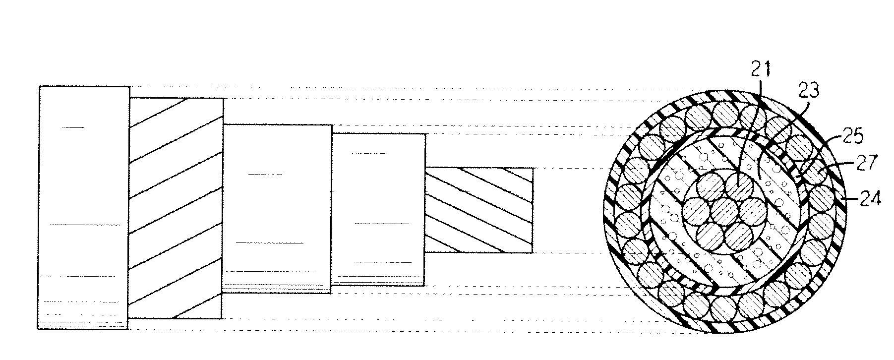
[0021]A micro coaxial cable according to the present invention includes an over-foaming preventing layer formed to surround an insulation layer, so foaming cells formed in the insulation layer are successively adjacently formed with a uniform size. Due to the uniformity of foaming, a dielectric constant in the insulation layer is uniform as a whole without showing any local difference, thereby giving excellent transmission characteristics.

[0022]The micro coaxial cable ac...


PUM

PropertyMeasurementUnit
diameteraaaaaaaaaa
sizeaaaaaaaaaa
thicknessaaaaaaaaaa

Abstract

A micro coaxial cable includes an inner conductor; an insulation layer having foaming cells and formed to surround the inner conductor; an over-foaming preventing layer formed to surround the insulation layer for the purpose of uniform forming of the foaming cells; a metal shield layer formed to surround the over-foaming preventing layer; and a protective coating layer formed to surround the metal shield layer.

Description

BACKGROUND OF THE INVENTION[0001]1. Field of the Invention[0002]The present invention relates to a micro coaxial cable, and more particularly to a micro coaxial cable in which foaming cells are formed uniformly in an insulation layer not to show any local difference of dielectric constant in the insulation layer, thereby giving excellent transmission characteristics.[0003]2. Description of the Related Art[0004]A coaxial cable includes a center conductor for transmitting signals, and an outer conductor coaxially formed on the center conductor, and many coaxial cables have been developed in various sizes and various kinds. The coaxial cable is generally used for transmitting signals to CATV or underground antennas. The development of coaxial cables has been mainly directed to a structural design between the center and outer conductors for reducing loss of energy, improvement of dielectric characteristics, and endowment of various schemes to an outside of the outer conductor.[0005]In p...

Claims


Application Information

Patent Timeline
Patent Type & Authority Patents(United States)
IPC IPC(8): H01B7/00
CPCH01B11/1869H01B11/12H01B11/18H01B11/1839H01B11/1895H01B13/016
Inventor PARK, CHAN-YONGNAM, GI-JOONPARK, JUNG-WONKIM, IN-HAKIM, JUNE-SUNSEO, IL-GUNLEE, GUN-JOO
Owner HITACHI METALS LTD
Features
  • R&D
  • Intellectual Property
  • Life Sciences
  • Materials
  • Tech Scout
  • Unparalleled Data Quality
  • Higher Quality Content
  • 60% Fewer Hallucinations
Learn More