Electric power converter and motor driving system

a technology of motor driving system and power converter, which is applied in the direction of electric generator control, dynamo-electric converter control, dynamo-electric gear control, etc., can solve the problems of large compensation error, increased compensation error, and difficulty in accurately performing the process of estimating the resistance in the high-speed rotation range. , to achieve the effect of improving accuracy and improving accuracy

Inactive Publication Date: 2009-06-02
HITACHI LTD
View PDF16 Cites 15 Cited by
  • Summary
  • Abstract
  • Description
  • Claims
  • Application Information

AI Technical Summary

Benefits of technology

[0010]An object of the present invention is to provide an electric power converter which has improved accuracy in compensation of a dead time, and a motor driving system employing the electric power converter.
[0012]With those features, the accuracy in compensation of the dead time can be improved.
[0013]Thus, according to the present invention, it is possible to perform compensation of the dead time with improved accuracy.

Problems solved by technology

However, the method disclosed in JP-A-5-64457 has the problems as follows.
Since a constant voltage is always added in spite of such a property, a compensation error is large.
Nevertheless, such a point is not compensated and hence the compensation error is increased.
If the impedance of the motor is assumed to be the resistance (R), it is difficult to accurately perform the process of estimating the resistance in the high-speed rotation range.
Thus, the compensation error is increased.

Method used


Image

  • Electric power converter and motor driving system
  • Electric power converter and motor driving system
  • Electric power converter and motor driving system

Examples


Embodiment Construction

[0020]The construction and operation of an electric power converter according to one embodiment of the present invention will be described below with reference to FIGS. 1 to 6.

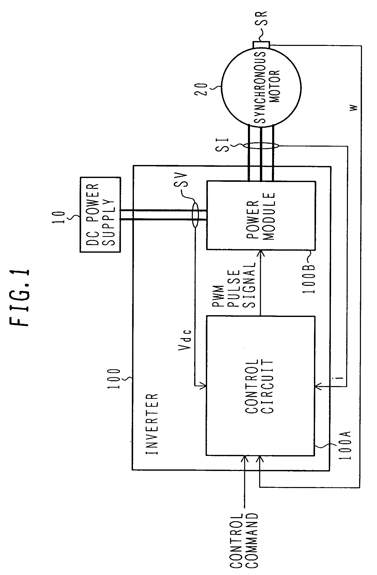
[0021]First, the construction of a motor driving system using an inverter, which is the electric power converter according to this embodiment, will be described below with reference to FIG. 1. The motor driving system of this embodiment is used in drive control for a synchronous motor (AC electric motor) mounted in, e.g., an electric or hybrid vehicle.

[0022]FIG. 1 is a block diagram of the motor driving system using the inverter which is the electric power converter according to the one embodiment of the present invention.

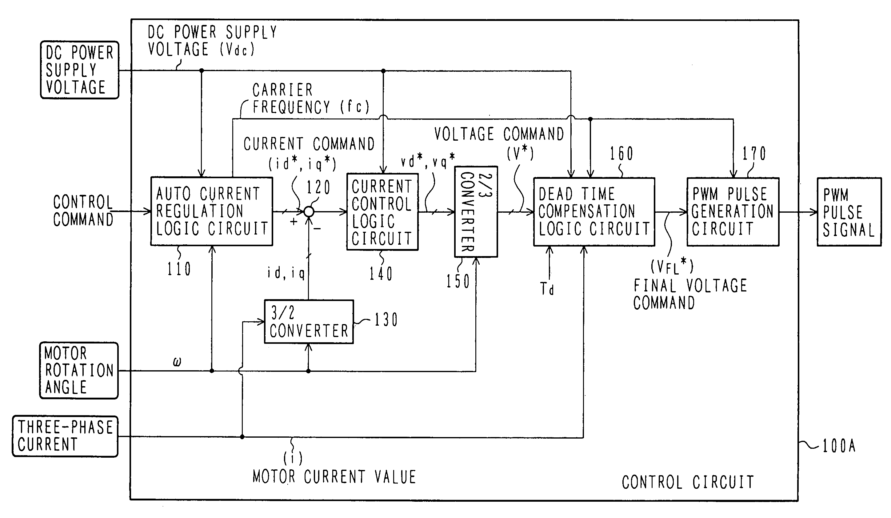
[0023]An inverter 100 converts DC power outputted from a DC power supply 10 to AC power and supplies the converted AC power to a synchronous motor (AC electric motor) 20, thereby driving the synchronous motor 20. The inverter 100 comprises a control circuit 100A and a power module 100B. The c...


PUM


Abstract

An electric power converter which has improved accuracy in compensation of a dead time. A motor driving system employing the electric power converter is also provided. A power module includes a plurality of switching devices connected in series and converts DC power to AC power. A control circuit produces a voltage command value in accordance with a control command inputted from the exterior, and produces gate signals to drive the switching devices of the power module corresponding to a final voltage command value which is obtained from the voltage command value with dead time compensation. A dead time compensation logic circuit calculates a final dead time compensation voltage based on a change rate of the voltage command value, a gain (dead time compensation voltage value), and a polarity of a current, the gain being calculated from a DC voltage value supplied to the electric power converter, a dead time, and a switching frequency.

Description

BACKGROUND OF THE INVENTION[0001]1. Field of the Invention[0002]The present invention relates to an electric power converter for converting DC power to AC power and in a motor driving system employing the electric power converter. More particularly, the present invention relates to an electric power converter suitable for compensating a dead time set in a drive signal for driving a semiconductor switching device, and to a motor driving system employing the electric power converter.[0003]2. Description of the Related Art[0004]An electric power converter, such as an inverter, is used to convert a DC voltage to an AC voltage by switching upper and lower switching devices, which are connected in series, with pulse width modulation (PWM), for example, and to drive an AC electric motor. If the upper and lower switching devices are turned on at the same time, an overcurrent flows with short-circuiting between the upper and lower switching devices, thus resulting in damages of those switchi...

Claims


Application Information

Patent Timeline
Patent Type & Authority Patents(United States)
IPC IPC(8): H02P27/04H02M7/48H02P21/00H02P21/05H02P21/22H02P23/04H02P25/022H02P25/026H02P27/08
CPCH02M7/53875H02M2001/385H02P21/00H02M1/385
Inventor NAWA, MASAMICHISAWADA, TAKEFUMI
Owner HITACHI LTD
Why Eureka
Try Eureka