Switch for vehicles

a technology for vehicles and switches, applied in the direction of contact mechanisms, pulse techniques, instruments, etc., can solve the problems of increasing the number of used components, consuming a lot of time for assembling, and the construction of switches becomes so complex, and achieves the effect of simple construction and simple construction

Active Publication Date: 2009-06-02
PANASONIC CORP
View PDF2 Cites 6 Cited by
  • Summary
  • Abstract
  • Description
  • Claims
  • Application Information

AI Technical Summary

Benefits of technology

[0019]Accordingly, it is an object of the present invention to provide a switch for vehicles which can perform various controls through a simple construction.
[0020]The switch for vehicles according to the invention includes a first switching device which performs the electrical connection / disconnection between a battery and a stop lamp and a second switching device connected to a control device which opens and closes the first switching device based on the magnitude of the magnetism of a magnet mounted on an operating body. Since various controls such as auto-cruise control and so on as well as the turn on / off of the stop lamp can be simultaneously performed by the one magnet mounted on the operating body, it is possible to obtain a switch for vehicles which can perform various operations through a simple construction.

Problems solved by technology

In the conventional switch for vehicles, however, since the turn-on / off of the stop lamp is controlled by magnet 3 and detection device 6 and the operation and stoppage of the auto-cruise device are controlled by movable contact 11 and fixed contacts 12, the number of used components increases, and the construction of the switch becomes so complex that assembling takes a lot of time.

Method used


Image

  • Switch for vehicles
  • Switch for vehicles
  • Switch for vehicles

Examples


first embodiment

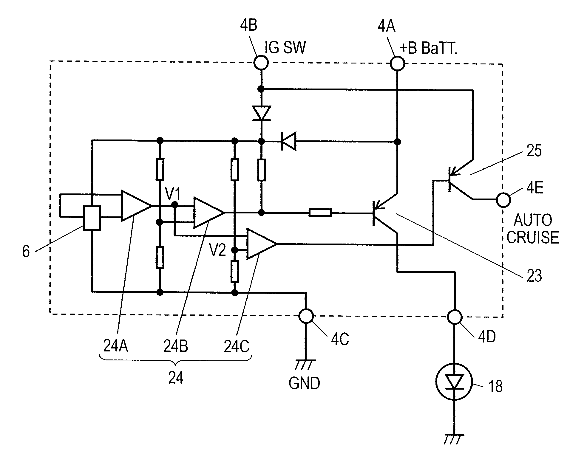
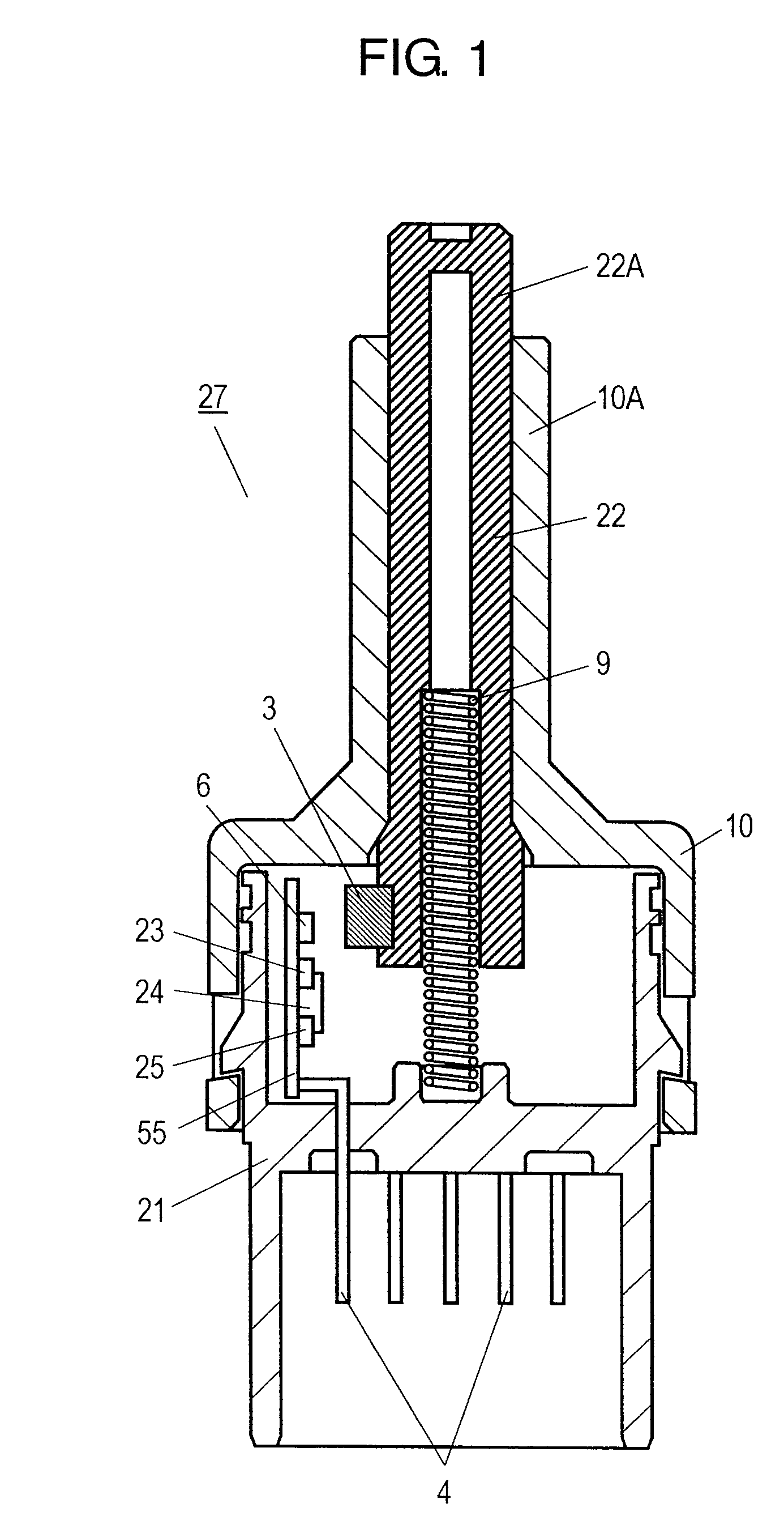
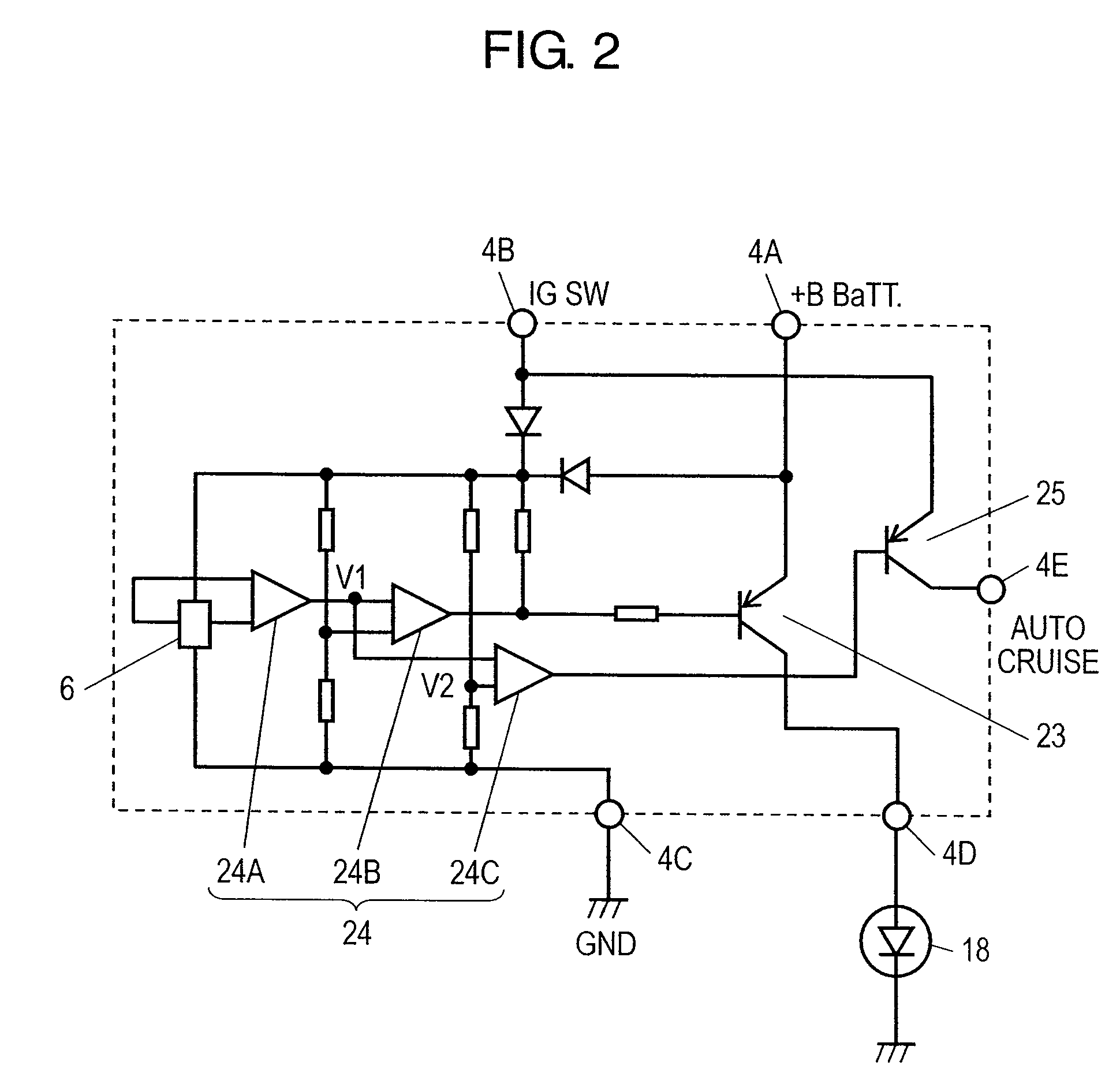
[0028]FIG. 1 is a cross-sectional view of a switch for vehicles according to the first embodiment of the invention. FIG. 2 is a circuit diagram of the switch for vehicles according to the first embodiment of the invention. In FIGS. 1 and 2, case 21 is formed in a box shape of which the top surface is opened, and is formed of insulating resin such as polybutylene terephthalate or ABS. Inside case 21, cylindrical operating body 22 which is formed of insulating resin is housed so as to vertically move. Further, operating body 22 has magnet 3 mounted on a lower left side surface thereof.

[0029]A plurality of terminals 4 are formed of conductive metal such as a copper alloy. Wiring substrate 55 has a plurality of wiring patterns (not shown) formed on the left and right surfaces thereof. Further, wiring substrate 55 is disposed at the left side wall of case 21, and the upper ends of terminals 4 are connected to the wiring patterns of wiring substrate 55 by soldering or the like. Further, t...


PUM


Abstract

Provided is a switch for vehicles, including a first switching device which performs the electrical connection / disconnection between a battery and a stop lamp and a second switching device connected to a control device which opens and closes the first switching device based on the magnitude of the magnetism of a magnet mounted on an operating body. Various controls such as auto-cruise control and so on as well as the turn on / off of the stop lamp can be simultaneously performed by the one magnet mounted on the operating body of the switch for vehicles.

Description

BACKGROUND OF THE INVENTION[0001]1. Field of the Invention[0002]The present invention relates to a switch for vehicles, which is used for controlling the turn-on / off of a stop lamp when operating a brake pedal of a vehicle.[0003]2. Description of the Related Art[0004]Recently, a pressing-operation-type switch for vehicles is frequently used for controlling a stop lamp in accordance with the operation of a brake pedal. Specifically, the switch for vehicles turns on the stop lamp when the brake pedal is stepped on, and turns off the stop lamp when the brake pedal is not stepped on.[0005]Such a conventional switch for vehicles will be described with reference to FIGS. 4 and 5.[0006]FIG. 4 is a cross-sectional view of a conventional switch for vehicles. In FIG. 4, case 1 is formed in a box shape of which the top surface is opened and is formed of insulating resin. Operating body 2 is housed in case 1 so as to vertically move. Further, operating body 2 has magnet 3 mounted on a lower lef...

Claims


Application Information

Patent Timeline
Patent Type & Authority Patents(United States)
IPC IPC(8): H01H9/00H01H3/14
CPCH03K17/80H03K17/97H03K17/60H03K2217/0036
Inventor SHIMIZU, MASARUSASANOUCHI, KIYOTAKA
Owner PANASONIC CORP
Why Eureka
Try Eureka