Measuring instrument and method for detecting a force

a technology of measuring instruments and force, applied in the direction of instruments, force/torque/work measurement apparatus, mechanical control devices, etc., can solve the problem of not being able to learn what the driver is asking for on the basis of the travel signal, using known travel measuring devices, etc., to achieve the effect of convenient disposal and easy installation

Inactive Publication Date: 2009-06-09
ROBERT BOSCH GMBH
View PDF13 Cites 2 Cited by
  • Summary
  • Abstract
  • Description
  • Claims
  • Application Information

AI Technical Summary

Benefits of technology

[0005]A measuring instrument according to the invention for detecting a force has the advantage over the prior art that a direct detection of what the driver is asking for is possible. On the basis of the direct detection of what the driver is asking for, it is also possible to use a smaller brake booster. There is also less hysteresis, and simpler regulation of braking delay is possible. Braking onset events, that is, states at the onset of the braking event, can also be detected early. Advantageously, the output signal of a measuring instrument of the invention for detecting a force also has high dynamics. As a result, especially advantageously, the signal can be used in the functions of a braking assist. When a force measuring instrument is used in combination with a travel sensor and pressure sensors, optimal control and monitoring of a wheel brake system of a motor vehicle (driver warning, servicing information notices, diagnostic memory) can advantageously be achieved. Since the measuring instrument of the invention for detecting a force has a tongue element protruding from a carrier plate, and the tongue element can be connected to a pedal plate, for instance, the measuring instrument of the invention can be installed directly on the pedal plate. This makes it possible to avoid the disadvantages of installing a measuring instrument on the foot pedal mechanism of the pedal lever. Moreover, the force measuring instrument of the invention, because it is mounted directly on the brake pedal, can be used in the most various pedal geometries without structural changes.
[0006]A measuring instrument according to the invention for detecting a force Has the advantage over the prior art that a direct detection of what the driver is asking for is possible. On the basis of the direct detection of what the driver is asking for, it is also possible to use a smaller brake booster. There is also less hysteresis, and simpler regulation of braking delay is possible. Braking onset events, that is, states at the onset of the braking event, can also be detected early. Advantageously, the output signal of a measuring instrument of the invention for detecting a force also has high dynamics. As a result, especially advantageously, the signal can be used in the functions of a braking assist. When a force measuring instrument is used in combination with a travel sensor and pressure sensors, optimal control and monitoring of a wheel brake system of a motor vehicle (driver warning, servicing information notices, diagnostic memory) can advantageously be achieved. Since the measuring instrument of the invention for detecting a force has a tongue element protruding from a carrier plate, and the tongue element can be connected to a pedal plate, for instance, the measuring instrument of the invention can be installed directly on the pedal plate. This makes it possible to avoid the disadvantages of installing a measuring instrument on the foot pedal mechanism of the pedal lever. Moreover, the force measuring instrument of the invention, because it is mounted directly on the brake pedal, can be used in the most various pedal geometries without structural changes.
[0007]By the disposition of a magnet on the tongue element of the force measuring instrument or on the carrier plate of the force measuring instrument, a simple, space-saving design can be achieved.

Problems solved by technology

Using known travel measuring devices is disadvantageous in the sense that a constant association of the ratio of the travel to the force is not possible.
That is, what the driver is asking for cannot be learned on the basis of the travel signal.
Moreover, this requires mounting on the foot pedal mechanism of the pedal, which can lead to unfavorable installation geometries in the area of the pedal.
In the use of pressure measuring instruments for detecting the brake pedal force, however, it is disadvantageous that what the driver is asking for is not immediately obtainable.
In addition, the (damping-dependent) dynamics of the pressure measuring instrument are relatively poor, and an output signal with relatively pronounced hysteresis is obtained.

Method used


Image

  • Measuring instrument and method for detecting a force
  • Measuring instrument and method for detecting a force
  • Measuring instrument and method for detecting a force

Examples


Embodiment Construction

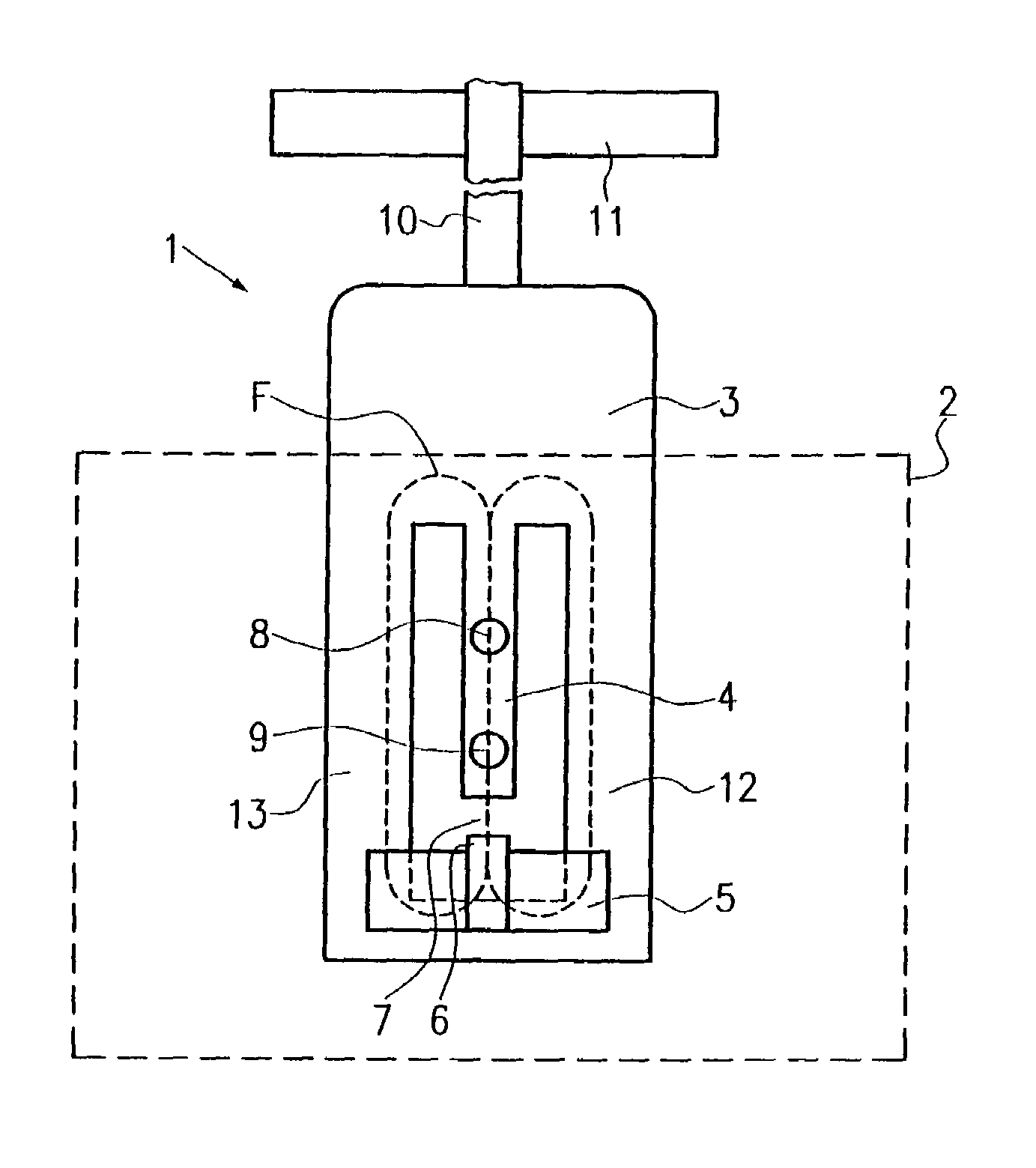
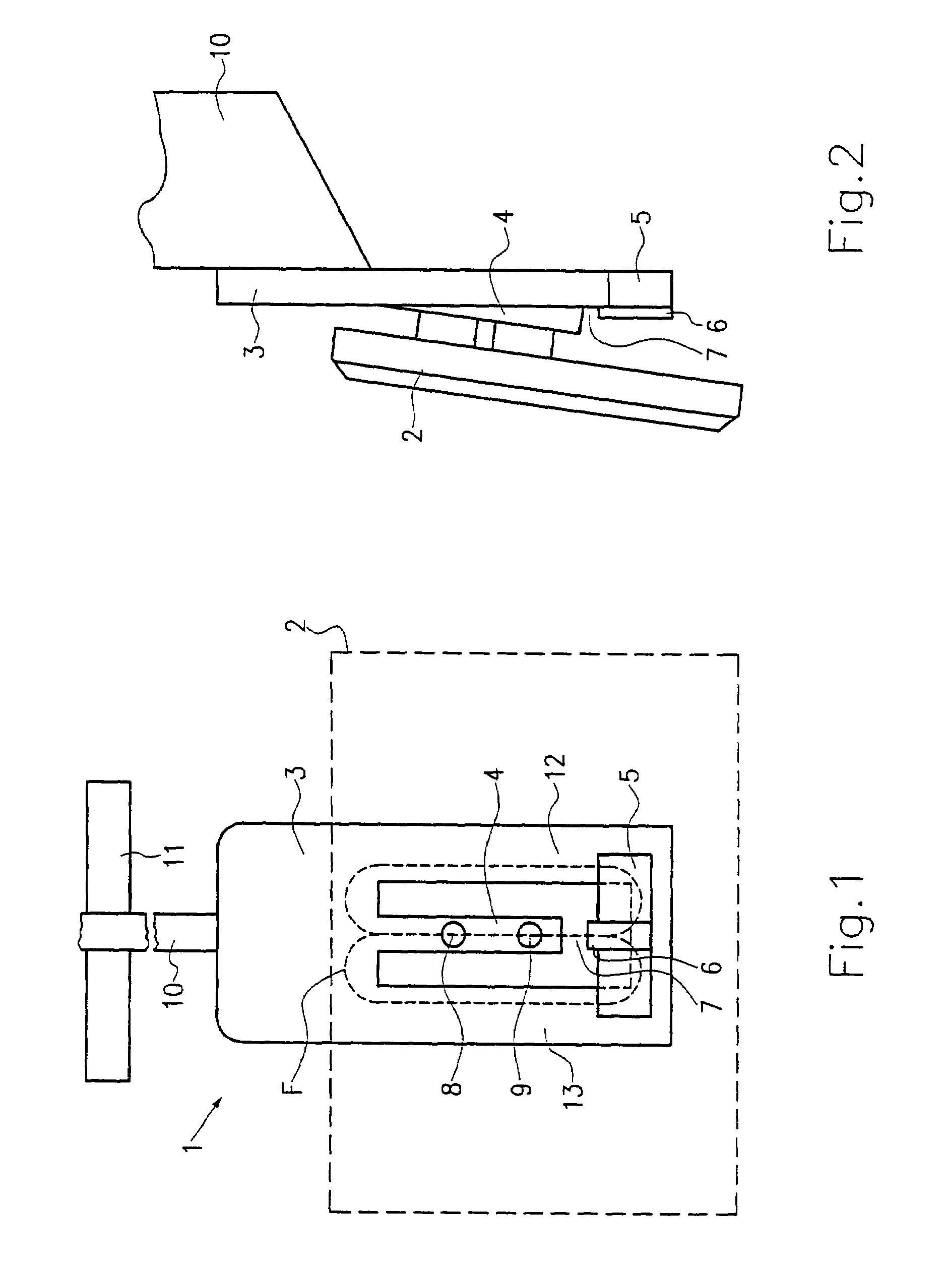
[0025]In FIGS. 1 and 2, a first exemplary embodiment of the force measuring instrument of the invention is shown. This force measuring instrument 1 is used in a pedal assembly of a motor vehicle. As shown in FIG. 1, the force measuring instrument 1 includes a carrier plate 3 and a tongue element 4. The tongue element 4 is formed integrally with the carrier plate 3 and is made for instance by stamping. As shown in FIG. 2, the tongue element 4 protrudes partly from the carrier plate 3. The tongue element 4 is embodied resiliently, so that when the pedal is not actuated, the tongue element returns to its outset position. The tongue element 4 also has two through openings 8 and 9, through which bolts are guided in order to join the tongue element 4 to a pedal plate 2.

[0026]As shown in FIG. 1, the tongue element 4 is embodied in barlike fashion, and an air gap 7 is formed between the tongue element 4 and the carrier plate 3. A magnetically sensitive element 6, such as a Hall element or a...


PUM

PropertyMeasurementUnit
forcesaaaaaaaaaa
forcesaaaaaaaaaa
force measuringaaaaaaaaaa

Abstract

The present invention relates to a force measuring instrument, having a carrier plate (3), at least one magnet (5), and at least one magnetically sensitive element (6). A tongue element (4) protrudes at least partly from the carrier plate (3) and is joined to a plate element (2). Between the tongue element (4) and the carrier plate (3), an air gap (7) is formed, in which the magnetically sensitive element (6) is positioned. The force to be measured, delivered via the plate element (2), leads to a relative motion between the end, toward the air gap, of the tongue element (4) and the carrier plate (3). This causes a change in the magnetic field geometry in the air gap (7). The present invention also relates to a method for detecting a force.

Description

CROSS-REFERENCE[0001]The invention described and claimed hereinbelow is also described in PCT / DE 01 / 00591, filed on Feb. 16, 2001 and DE 100 09 168.7, filed on Feb. 26, 2000. This German Patent Application, whose subject matter is incorporated here by reference, provides the basis for a claim of priority of invention under 35 U.S.C. 119(a)-(d).BACKGROUND OF THE INVENTION[0002]The invention relates to a measuring instrument for detecting a force and to a method for detecting a force. In particular, the present invention relates to a measuring instrument and to a method for detecting a pedal force, exerted by a driver, in a vehicle.[0003]Lately, particularly in the automotive field, ever-increasing numbers of electronic systems are being used, such as anti-lock brake systems, traction control systems, or electronic brake systems. Especially for electronic brake systems, it is necessary for the force exerted on the brake pedal by the driver to be detected as precisely as possible, so t...

Claims


Application Information

Patent Timeline
Patent Type & Authority Patents(United States)
IPC IPC(8): G01L1/00B60T7/02B60T7/04G01D5/14G01D5/16G01L1/14G01L1/26G01L5/22G05G1/30
CPCB60T7/042G01D5/145G01L1/14G01L5/225
Inventor HOFSAESS, MICHAEL
Owner ROBERT BOSCH GMBH
Why Eureka
Try Eureka