Ventilation unit

a technology of ventilation unit and ventilation means, which is applied in the direction of vehicle maintenance, building components, seating furniture, etc., can solve the problems of uncomfortable direct flow onto the vehicle occupants by way of directed air flow, and achieve the effects of space-saving and inexpensive, simple assembly and disassembly, and improved operational ergonomics

Inactive Publication Date: 2009-06-09
FAURECIA INNENRAUM SYST
View PDF17 Cites 5 Cited by
  • Summary
  • Abstract
  • Description
  • Claims
  • Application Information

AI Technical Summary

Benefits of technology

[0006]Thus different displacement conditions may be easily set for setting predefined flow exit angles. The first and second components which for this are movable relative to one another may be kept very simple with regard to design and despite this offer a multitude of possibilities for ventilating the vehicle. Thus it is simply possible to provide a ventilation / air conditioning of the interior with a directed air flow (the production of diffuse air flows will be dealt with at a later point). Furthermore it is also possible to achieve a de-icing (“defrosting”) of the windscreen with a directed air flow. A further advantage lies in the fact that with this simple design embodiment, the flow exit opening may be created over the whole width of the instrument panel (dashboard) and thus of the vehicle interior. Furthermore, in the region which may be reached by the arms of the vehicle occupants one requires a smaller surface (area) for the supply of fresh air, so that the surfaces which become vacant may be used for other purposes (e.g. navigation systems etc.)
[0007]Concluding, the invention thus offers the advantages that it is space-saving and inexpensive, permits a simple assembly and disassembly, that it may be manufactured in a modular construction manner and may render possible improved operational ergonomics as well as an improved “thermal comfort” in the interior of the vehicle.
[0008]One advantageous development envisages the first and / or second component having a grid shape. With this its becomes easily possible to realise several flow exit channels arranged parallel to one another on a larger length, which e.g. may be easily accommodated in the corner region between the instrument panel (dashboard) and the windscreen.

Problems solved by technology

Disadvantages however result on account of the large space requirement, as well as under certain circumstances on account of the complicated design of the closure or pivot mechanisms.
A further disadvantage lies in the fact that a direct flow onto the vehicle occupants by way of the directed air flow is often perceived as being uncomfortable.

Method used


Image

  • Ventilation unit
  • Ventilation unit
  • Ventilation unit

Examples


Embodiment Construction

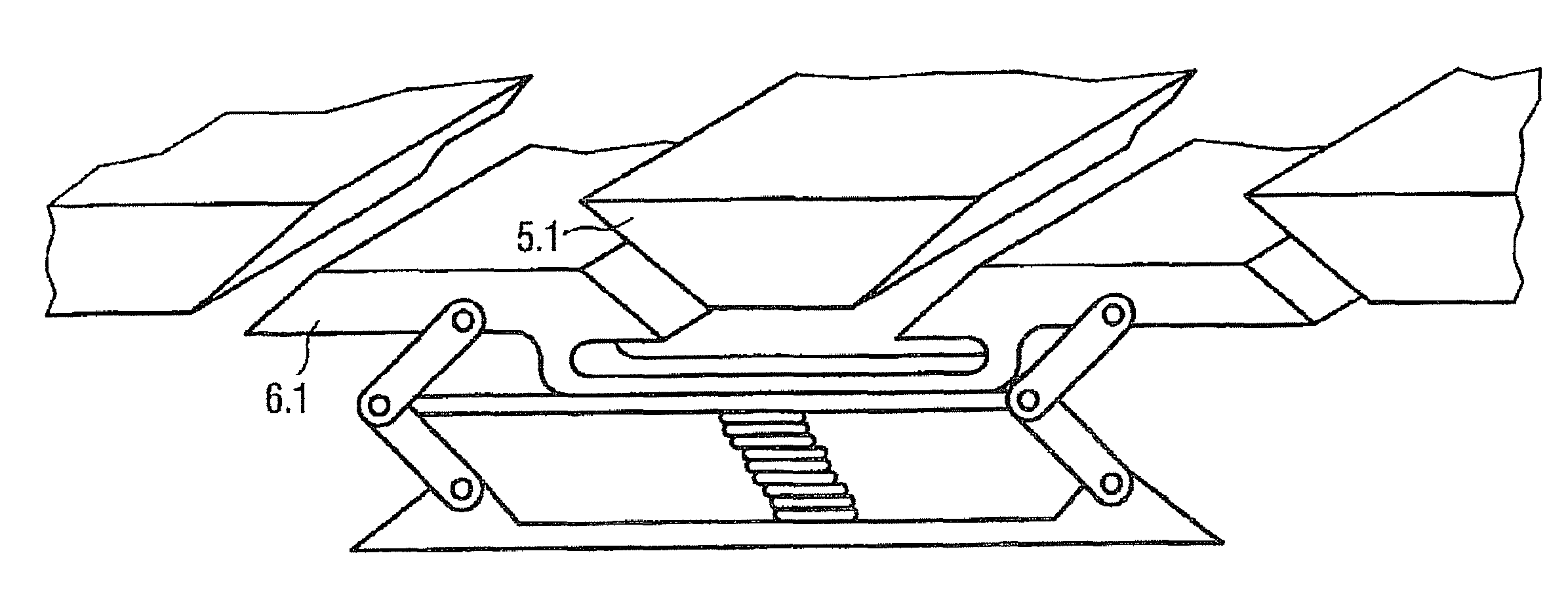
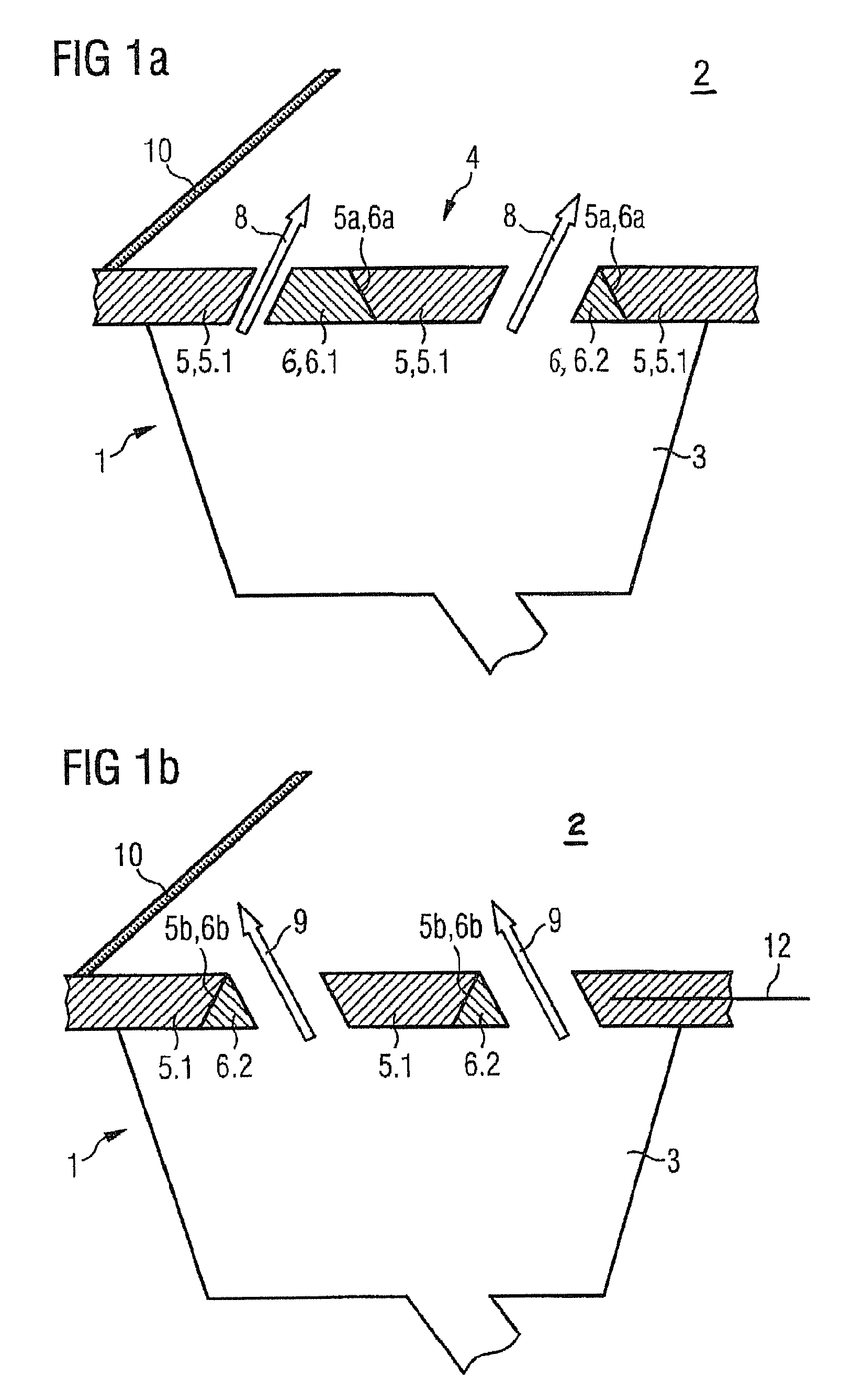
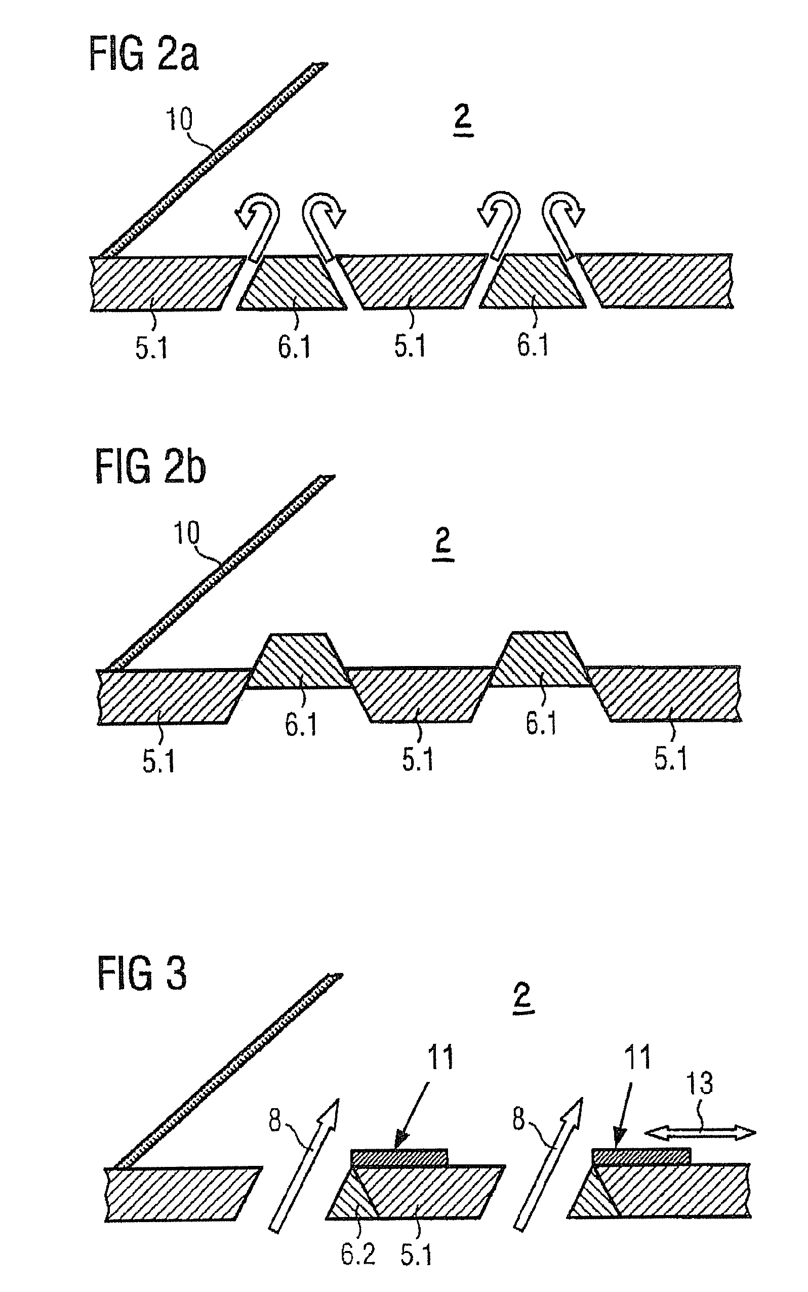
[0030]FIG. 1a shows a ventilation means 1 according to the invention. This is accommodated within a motor vehicle interior 2 which is limited to the front by a windscreen 10. The ventilation means comprises an air supply channel 3 which is connected to an air conditioning installation or likewise, which is not shown here. The air supply channel 3 may be connected to the interior of the motor vehicle via a flow exit region 4. A first component 5 which is rigidly connected to the instrument panel (dashboard) is shown in cross section in the flow exit region 4. This component comprises webs 5.1 which run in the vertical axis to the plane of the sheet and which have an essentially parallelogram-like cross section over the complete length of the web. The parallelograms at the same time are directed downwards with their smaller cover surface so that lateral inclinations arise which on the left side run from the top left to the bottom right, and on the right side from the top right to the ...


PUM


Abstract

A ventilation unit for a motor vehicle passenger compartment has an air feeding channel and an outflow area. The outflow area includes a first and second component that can be placed in different positions relative to each other. Various closing surfaces of the first and second components are variously positionable in relation to each other to produce air flows of differing angle into the passenger compartment.

Description

BACKGROUND OF THE INVENTION[0001]The present invention relates to a ventilation means / ventilation unit.[0002]It is already known to provide the interiors of motor vehicles with fresh air by way of ventilation channels which are to be opened and closed at the will of the user. Known systems e.g. have pivoting lamellae which are supplied by an air supply channel and e.g. may be closed by way of a rotary flap in the air supply channel. It is also possible to achieve the direction of the air flow by way of pivoting the lamellae.[0003]This known system basically functions in a satisfactory manner. Disadvantages however result on account of the large space requirement, as well as under certain circumstances on account of the complicated design of the closure or pivot mechanisms. A further disadvantage lies in the fact that a direct flow onto the vehicle occupants by way of the directed air flow is often perceived as being uncomfortable.[0004]It is therefore the object of the present inven...

Claims


Application Information

Patent Timeline
Patent Type & Authority Patents(United States)
IPC IPC(8): B60S1/54B60H1/34F24F13/12
CPCF24F13/12B60H1/34B60H1/3414B60H2001/3478
Inventor JAHN, THOMASMETZ, PETERDOLL, VOLKER
Owner FAURECIA INNENRAUM SYST
Why Eureka
Try Eureka