Small conformable broadband traveling-wave antennas on platform

a technology of broadband and traveling wave, applied in the field of radiofrequency antennas, can solve the problems of inability to meet most conformability requirements, inability to meet broadband and smallness/conformity inherently conflicting requirements, and limited bandwidth of antennas, so as to achieve the effect of enhancing the effective size of the antenna and enhancing the antenna gain bandwidth

Active Publication Date: 2009-06-09
WANG ELECTRO OPTO
View PDF5 Cites 10 Cited by
  • Summary
  • Abstract
  • Description
  • Claims
  • Application Information

AI Technical Summary

Benefits of technology

[0015]The novelty of the invention is in its elegant solution to circumvent the fundamental gain bandwidth limitations of an antenna of a given size and shape. The invention stems from a profound realization of the shortcomings of the well established theory on this topic. By using a traveling-wave antenna and strongly coupling it with the platform on which the antenna is mounted, the effective size of the antenna is enlarged and thus the antenna gain bandwidth is enhanced. This invention is to overcome the frequency bandwidth limitations, especially the lower bound of the frequency, in antennas mounted on a platform.

Problems solved by technology

Now, broadband and smallness / conformability are inherently conflicting requirements for antennas.
The bandwidth of an antenna is limited by its size, shape, and the interference of proximate objects.
Unfortunately the microstrip patch antenna is a narrowband antenna.
However, for a platform that is irregularly shaped, and / or has a small size and a small radius of curvature (in terms of the operating wavelength), these antennas have thus far been unable to satisfy most conformability requirements.
Additionally, the gain bandwidth of an antenna is fundamentally limited by its electrical size (namely, size in wavelength); thus broadband is difficult to achieve when the antenna is electrically small.
These severe shortcomings of the Chu theory are rooted in its basic assumptions which are overly narrow and incompatible with most real-world problems.
First, an antenna is rarely an object isolated in space; its specific size becomes ambiguous when it is mounted on a platform.
Since an antenna is always connected to a transmission line feeding a transceiver, its extent and size become ambiguous, especially if it is electrically small.
Second, in the Chu theory the antenna problem was formulated restrictively (strictly speaking, inadequately) as an antenna with an external matching network, with single-port connections between them and the transceiver.
Third, the Chu theory is applicable only to high-Q (quality factor) narrowband antennas because it is based on the inverse relationship between Q and bandwidth, which rapidly becomes invalid as Q decreases below about 4.
Fourth, the unrealistic assumption of zero dissipative loss makes it unamenable to the design approach which optimizes gain-bandwidth at a small sacrifice of dissipative loss.
The practical bandwidth limitation on the upper frequency bound is largely due to its radiation property (pattern and polarization); and at its lower frequency bound is due to its impedance.
However, these conformal TW antennas exceeding the Chu limitation are confined to the SMM antenna and the SW antenna, both of which have a conducting ground plane and a radiator fairly planar and spaced a constant distance apart.

Method used


Image

  • Small conformable broadband traveling-wave antennas on platform
  • Small conformable broadband traveling-wave antennas on platform
  • Small conformable broadband traveling-wave antennas on platform

Examples


Embodiment Construction

The Physical Structure

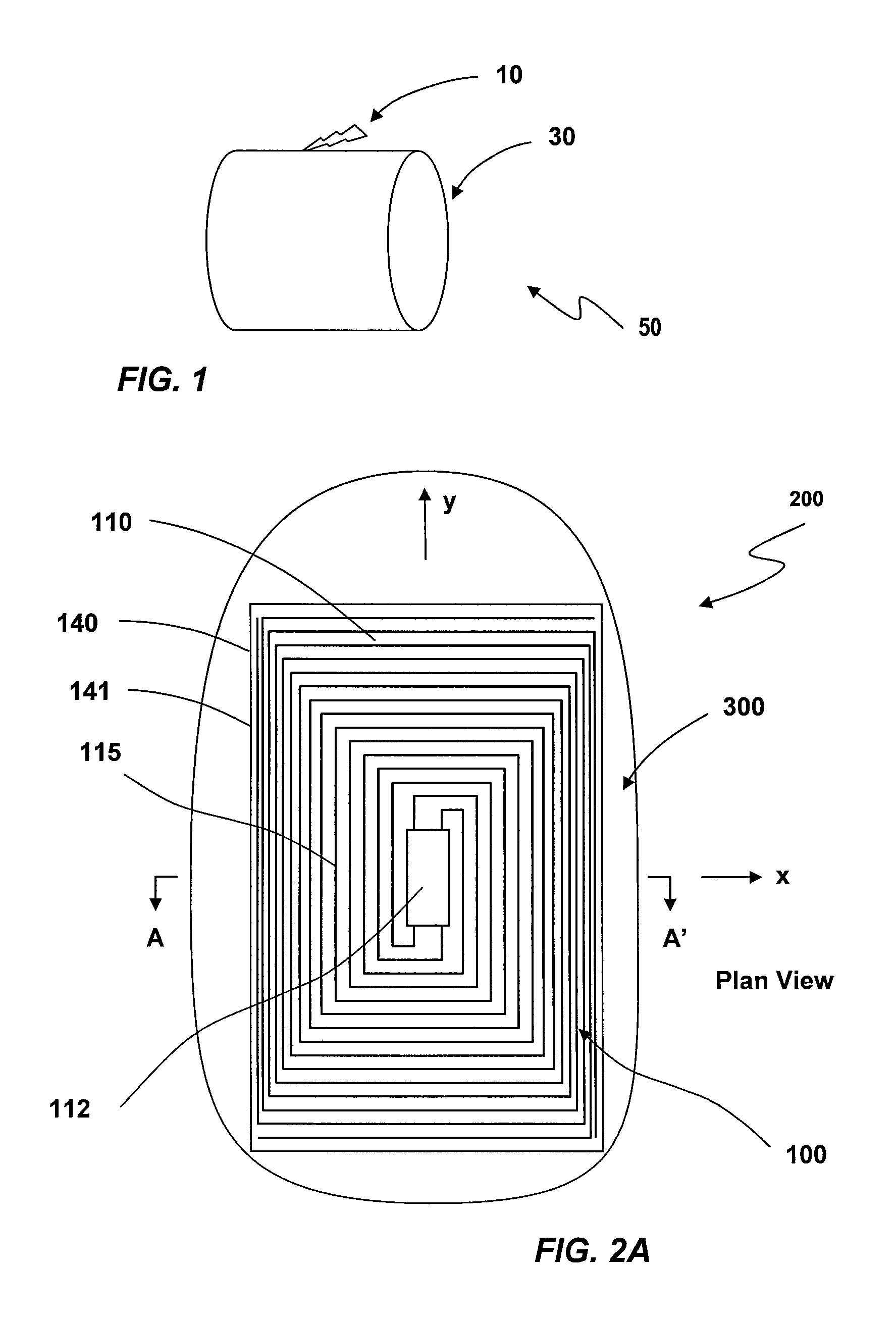
[0034]Referring now to FIG. 1 depicting an antenna 10 mounted on a platform 30, the antenna / platform assembly is collectively denoted as 50 in recognition of the inseparable interactions between the antenna 10 and its mounting platform 30, especially when the dimensions of the antenna are smaller than, say, ½ wavelength.

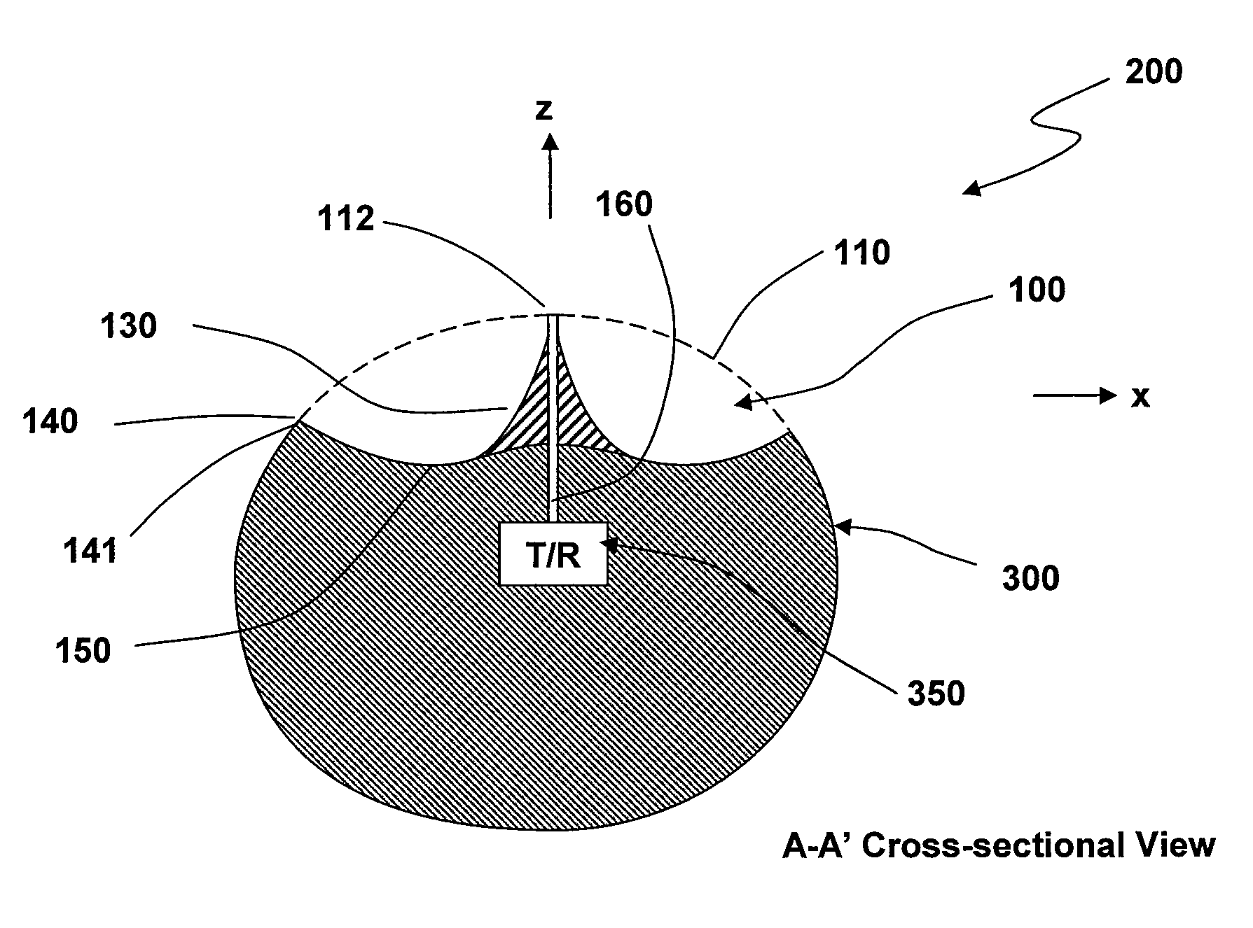
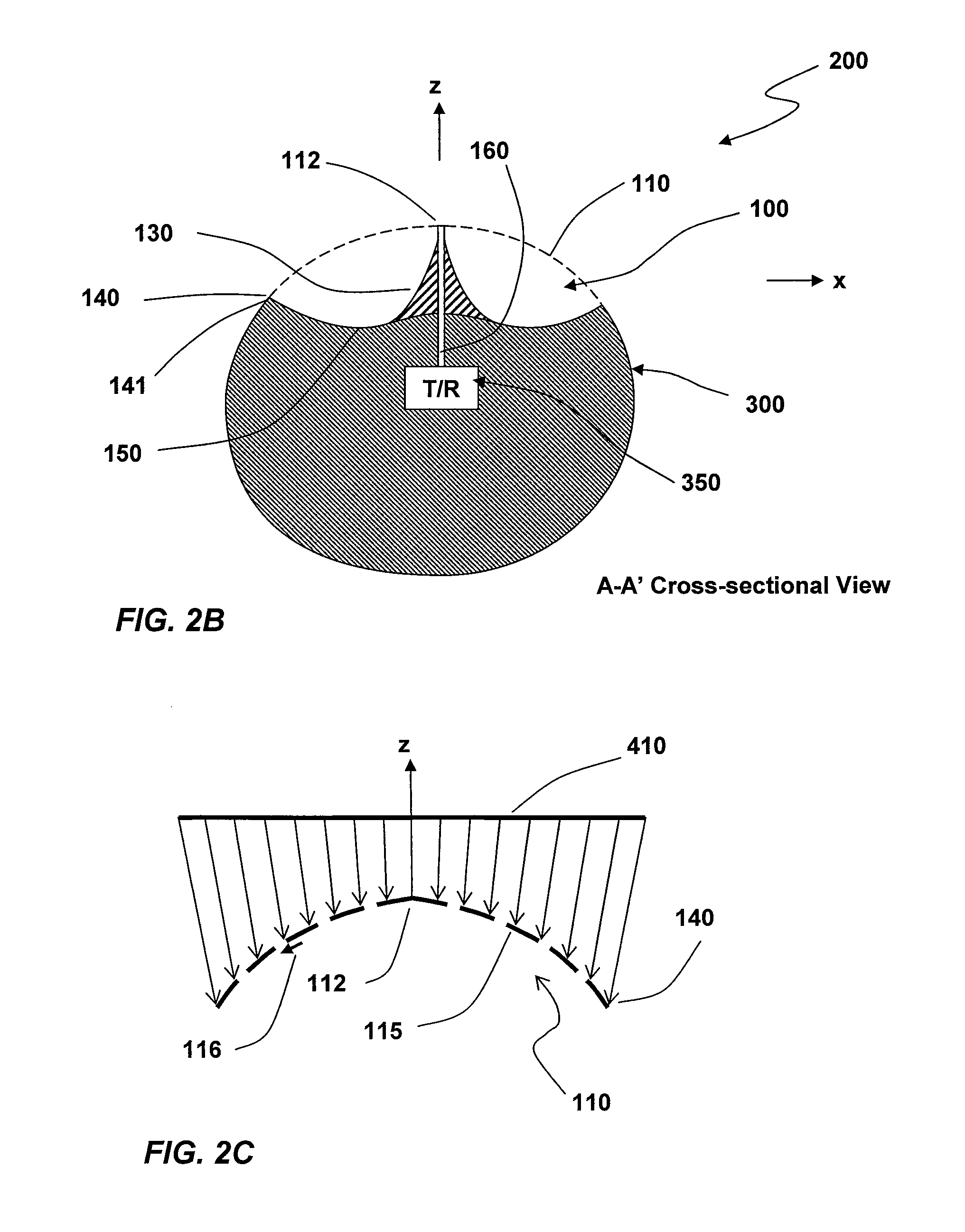
[0035]In a preferred form of this invention, a conformable broadband traveling-wave (TW) antenna coupled with a platform is depicted in the plan view in FIG. 2A and a cross-sectional view in FIG. 2B at the A-A′ plane of FIG. 2A. A broadband TW antenna 100 is conformally mounted on a platform 300, and as an integrated antenna / platform assembly 200. By conformal mounting it is generally meant that the antenna is a low-profile structure that can be integrated onto a platform with minimal intrusion and / or protrusion.

[0036]The broadband TW antenna 100 consists of a broadband TW surface radiator 110 positioned above and spaced from a conducting ground...


PUM


Abstract

The invention is a novel solution to circumvent the fundamental gain bandwidth limitations of an antenna of a given size by using a traveling-wave (TW) antenna and strongly coupling it with the mounting platform to enlarge the effective size of the antenna. A preferred form of this invention comprises a conducting ground surface generally curvilinear and conformal to said platform, a broadband TW surface radiator positioned above and spaced apart from said ground surface, an impedance matching structure between the surface radiator and the conducting ground surface, and a reactive impedance matching network positioned on the periphery of said surface radiator.

Description

STATEMENT REGARDING FEDERALLY SPONSORED RESEARCH OR DEVELOPMENT[0001]This invention was conceived and created by the inventor without external financial support. The inventor chose to assign all the rights to Wang Electro-Opto Corporation. Wang Electro-Opto Corporation chose to grant to the U.S. Department of Defense (DoD) the right for royalty-free usage similar to the terms and conditions of DoD SBIR (Small Business Innovation Research) program in recognition of the product development effort later using this invention under a DoD SBIR contract No. H92222-07-C-0071 sponsored by U.S. Special Operations Command, MacDill AFB, FL 33621.TECHNICAL FIELD[0002]The present invention is generally related to radio-frequency antennas and, more particularly, small conformal broadband antennas on curved platform.BACKGROUND OF THE INVENTION[0003]Small broadband antennas conformable to curved platforms have become increasingly more important for both military and commercial applications. The broa...

Claims


Application Information

Patent Timeline
Patent Type & Authority Patents(United States)
IPC IPC(8): H01Q13/10
CPCH01Q13/20
Inventor WANG, JOHNSON J. H.
Owner WANG ELECTRO OPTO
Why Eureka
Try Eureka