EMI reduced power inverter

a power inverter and electromagnetic interference technology, applied in the field of power inverters, can solve the problems of high electromagnetic interference (emi) noise in power supplies, incorrect data acquisition, and high frequency, and achieve the effect of reducing voltage fluctuation, effectively preventing, and reducing frequency

a power inverter and electromagnetic interference technology, applied in the field of power inverters, can solve the problems of high electromagnetic interference (emi) noise in power supplies, incorrect data acquisition, and high frequency, and achieve the effect of reducing voltage fluctuation, effectively preventing, and reducing frequency

US7547987B2Inactive Publication Date: 2009-06-16HITACHI AUTOMOTIVE SYST LTD

Image

  • EMI reduced power inverter
  • EMI reduced power inverter
  • EMI reduced power inverter

Examples


Embodiment Construction

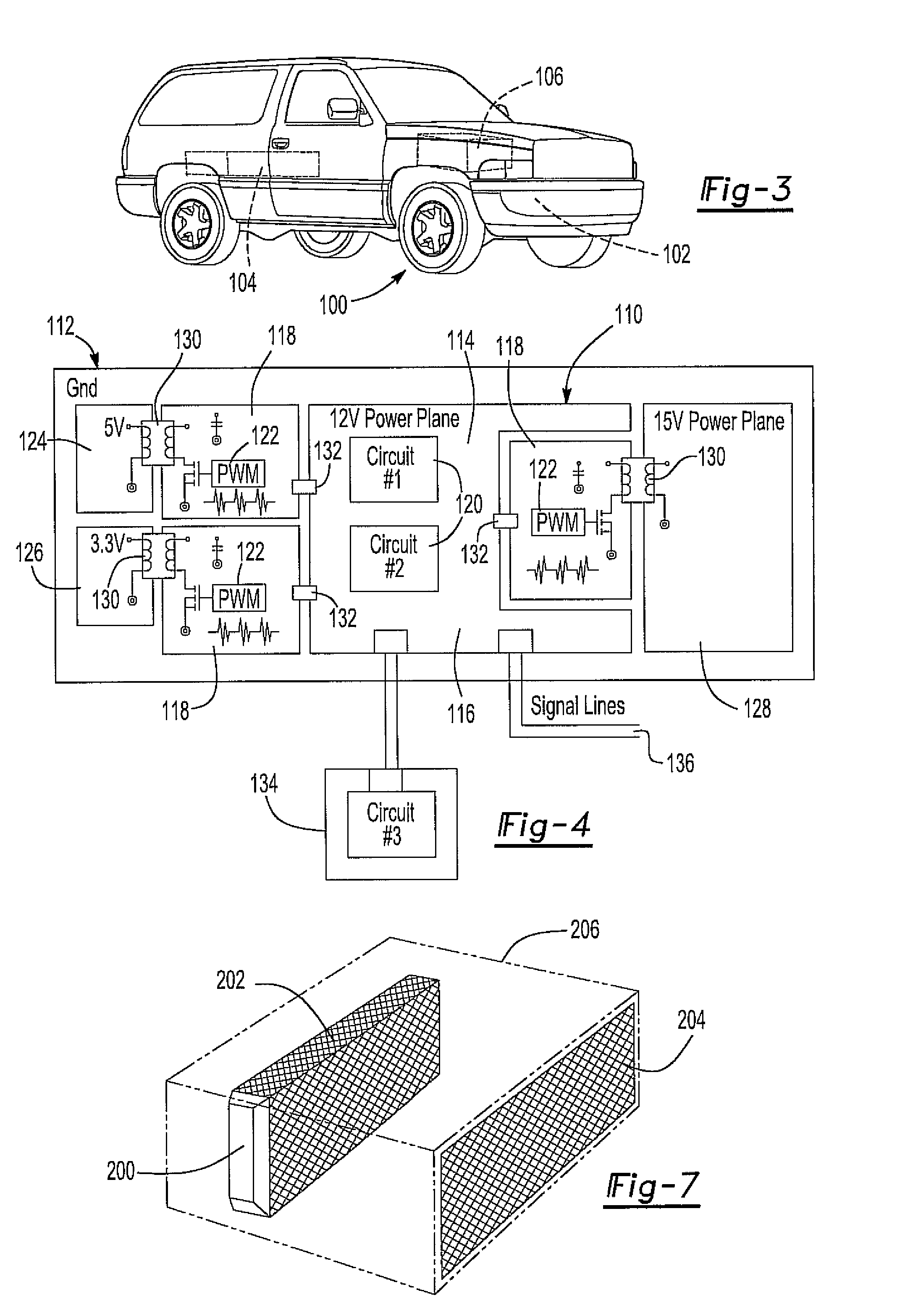
[0026]With reference first to FIG. 3, a hybrid electric vehicle (HEV) 100 is illustrated. The HEV includes not only a conventional internal combustion engine 102, but also an electric motor 104 which are selectively drivingly connected to the wheels of the vehicle 100 to propel it.

[0027]A power inverter 106 is mounted to the vehicle 100. Inside the power inverter module, there are many switching power supply functioning as DC-DC converter to provide the various electric voltages, typically 3.3 volts, 15 volts, 5 volts and 12 volts, used by the power inverter controller module in the HEV 100 during its operation.

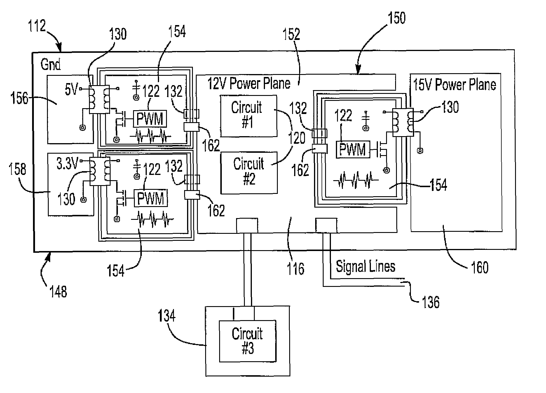
[0028]With reference now to FIG. 4, a power plane 110 of a printed circuit board 112 contained within the controller module of the power inverter 106 (FIG. 3) is shown. The power plane 110 includes a main power plane or layer 114 which is typically maintained at 12 volts.

[0029]Unlike the previously known power inverters, the main power layer 114 is divided into a first sectio...


PUM


Abstract

A power inverter of the type used with hybrid electric vehicles having a circuit board with a power layer having a first and second section which are electrically separated using slits from each other on the power layer. A control circuit is connected to and powered by the first section of the power layer while a switching power supply is connected to and powered by the second section of the power layer. An electromagnetic filter is electrically connected between the sections of the power layer. This electromagnetic filter blocks high frequency noises of the type generated by the switching power supply while enabling the sections to be maintained at the same DC voltage level. Optionally, a ferrite covering is provided around a current bus bar of the power inverter to contain magnetic fields generated by current flow through the bus bar.

Description

BACKGROUND OF THE INVENTION[0001]I. Field of the Invention[0002]The present invention relates generally to power inverters and, more particularly, to a power inverter having a switching power supply.[0003]II. Description of Related Art[0004]In a hybrid electric vehicle (HEV) an electric motor is utilized to assist the engine to provide more traction and also to regenerate power to charge the battery. For both driving and regenerating, a power inverter is utilized to complete the conversion between AC and DC.[0005]The power inverter constitutes the main electronic module in an HEV system. In such a system, a 12-volt source is the major power source voltage level for most of the automotive controller electronics. However, it is necessary to convert the 12-volt power source to other voltage levels in order to accommodate the other components of the HEV system. For example, typically, a 3.3-volt source is required for microcontrollers used in the HEV system while a 5-volt source is requ...

Claims


Application Information

Patent Timeline
16 Jun 2009
Publication
US7547987B2
IPC
B60L1/00; B60L3/00; H02G3/00
CPC
H02M1/44; H02M7/003; B60L2270/147
Inventors
TORIGOE, MAKATO; SHAO, LIANG