Soft switching DC-DC converter including a buck converter and a boost converter sharing a common transformer

a technology of buck converter and boost converter, which is applied in the direction of electric variable regulation, process and machine control, instruments, etc., can solve the problems of circuit size increase, circuit size increase, and lowering efficiency, so as to reduce the loss of capacitor operation, reduce the loss of switching, and achieve high frequency operation

Inactive Publication Date: 2009-06-23
HITACHI LTD
View PDF33 Cites 25 Cited by
  • Summary
  • Abstract
  • Description
  • Claims
  • Application Information

AI Technical Summary

Benefits of technology

[0096]The soft switching DC-DC converter according to the invention allows a substantial reduction of the loss in the capacitor operation, by including a resonant circuit composed of a transformer.
[0097]Further, the switching loss can be substantially reduced and a high frequency operation is possible, thereby allowing the size and cost reductions of the transformer and capacitor.

Problems solved by technology

The circuit disclosed in Patent Document 1, however, requires the resonant reactor and the auxiliary resonant circuit composed of an auxiliary switch and a diode for preventing reverse conduction, causing the size and cost increase of the circuit.
In addition, as electric current flows to the auxiliary resonant circuit of the auxiliary switch and diode that are serially connected, there has been concern that the occurrence of losses in the auxiliary switch and the diode could lead to the lowering of efficiency.
Further, as it requires a circuit for controlling the auxiliary switch and a power source circuit, there has been a problem of the circuit size increase.

Method used


Image

  • Soft switching DC-DC converter including a buck converter and a boost converter sharing a common transformer
  • Soft switching DC-DC converter including a buck converter and a boost converter sharing a common transformer
  • Soft switching DC-DC converter including a buck converter and a boost converter sharing a common transformer

Examples


embodiment 1

[0113]First of all, a first embodiment of the present invention will be described with reference to FIGS. 1 and 2.

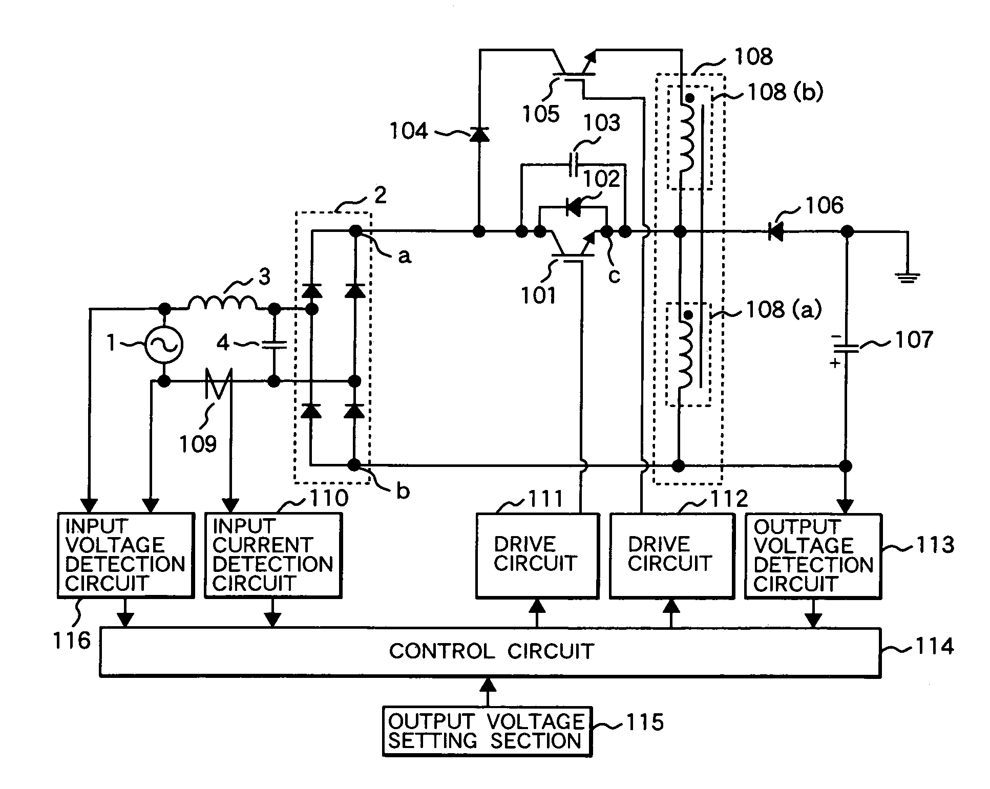
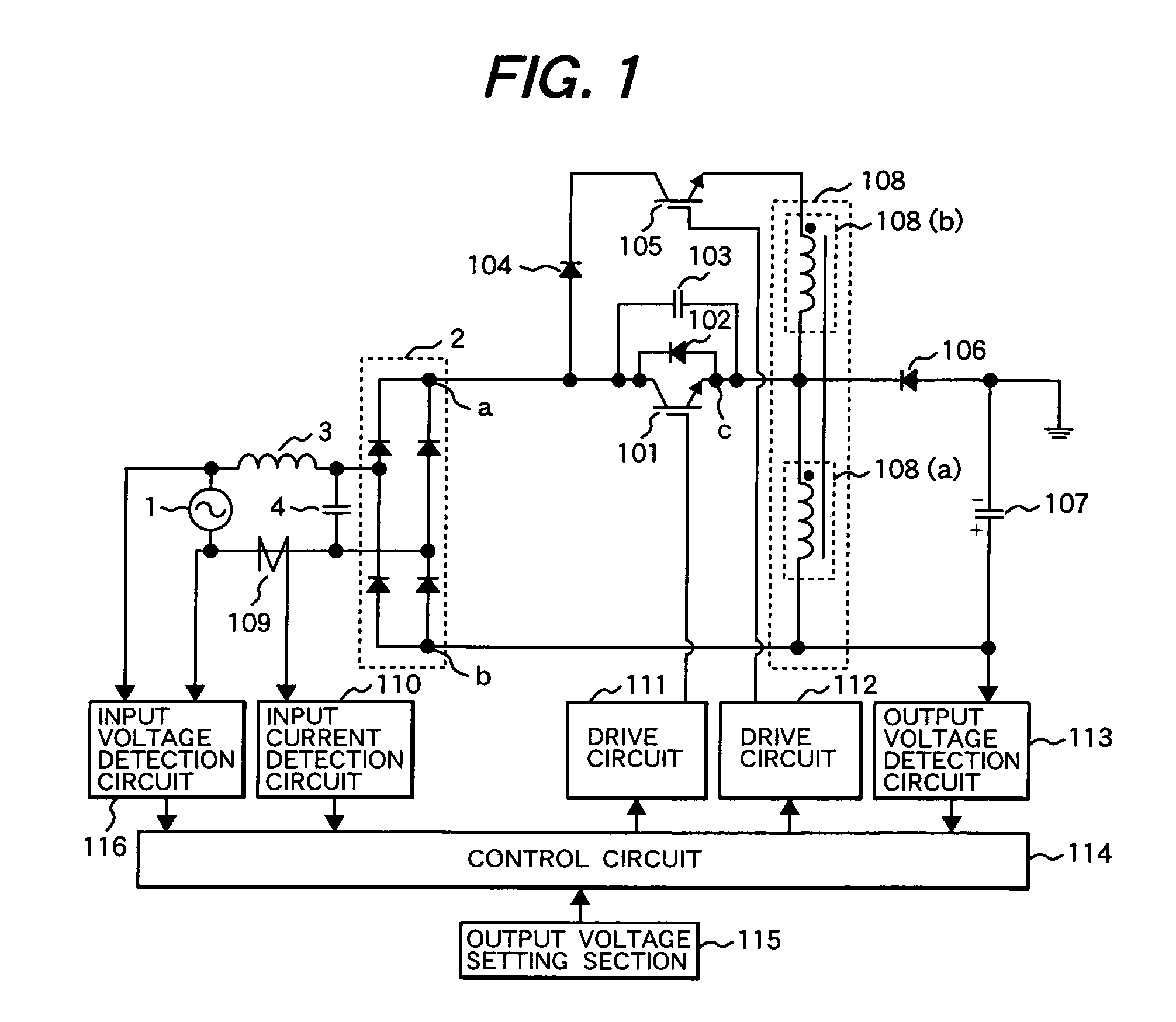
[0114]FIG. 1 is a circuit view of a soft switching DC-DC converter which is the first embodiment of the invention. This embodiment is a buck-boost converter allowing both the boost operation of outputting a voltage higher than the input voltage and the buck operation of outputting a voltage lower than the input voltage.

[0115]The configuration of FIG. 1 is described as follows: a commercial AC power source 1 is applied to a rectification circuit 2, full wave rectified, and converted into a DC current via a filter circuit composed of an inductor 3 with a coil and a capacitor 4. Herein, assuming the high potential side of the rectification circuit 2 is a point and the low potential side is b point, a point is connected with a collector terminal of an IGBT 101 as a main switching element, and the cathode and anode of a diode 102 are connected between the collector and emitte...

embodiment 2

[0121]FIG. 4 is a circuit view showing a second embodiment of the invention. This embodiment is a buck-type soft switching DC-DC converter. In FIG. 4, the same reference numerals are assigned to the same components as those in FIGS. 1 to 3.

[0122]The configuration of FIG. 4 will be described. In FIG. 4, the embodiment differs from embodiment 1 at the point where a cathode terminal of a diode 401 is connected to c point and an anode terminal of the diode 401 is connected to b point, and a primary coil 402a of a loose coupling transformer 402 is connected to c point and the positive electrode side of an output capacitor 107.

[0123]Next, the operations will be described. The operation when the IGBTs 101, 105 are in the turn-off state is the same as that in the first embodiment. When the IGBT 101 is turned on, the electric current flows to the IGBT 101, the transformer 402a , the capacitor 107 and the capacitor 4, as well as to the commercial AC power source 1, the rectification circuit 2...

embodiment 3

[0126]FIG. 6 is a circuit view showing a third embodiment of the invention. This embodiment is a boost-type soft switching DC-DC converter. In FIG. 6, the same reference numerals are assigned to the same components as those in FIGS. 1 to 5.

[0127]The configuration of FIG. 6 will be described. In FIG. 6, the inductor 3 is connected between a point and d point, the capacitor 4 is connected between d point and b point, a primary coil 608a of a transformer 608 is connected between d point and e point, and an IGBT 601 is connected between d point and b point, wherein a collector terminal of the IGBT 601 is connected to d point and an emitter terminal thereof is connected to b point. Connected to the collector terminal of the IGBT 601 is a cathode terminal of a diode 602, and connected to the emitter terminal of the IGBT 601 is an anode terminal of the diode 602. Further, a snubber capacitor 603 is connected in parallel to the IGBT 601. The anode terminal of the diode 604 is connected from...


PUM


Abstract

A soft switching DC-DC converter is provided which includes circuitry for both a buck converter and a boost converter. The buck converter circuitry and the boost converter circuitry share a common transformer including a primary coil and first and second secondary coils. A first switching element is coupled to a first capacitor to provide the buck converter operation while another switching element is provided to provide the boost converting operation. The primary coil of the transformer is commonly used as a choke coil by both the buck converter and the boost converter. In this way, size and cost reduction can be obtained.

Description

CLAIM OF PRIORITY[0001]The present application claims priority from Japanese application serial no. 2005-031216, filed on Feb. 8, 2005, the content of which is hereby incorporated by reference into this application.FIELD OF THE INVENTION[0002]The present invention relates to a soft switching DC-DC converter for converting a voltage of an input power into another voltage.BACKGROUND OF THE INVENTION[0003]A soft switching DC-DC converter for converting a voltage of an input power into a desired voltage to output can be highly improved in its efficiency by reducing switching loss with soft switching technology. Accordingly, it makes it possible to downsize the passive components such as a choke coil and a capacitor by making the drive frequency of a switching element higher. Thus, as an example of a conventional soft switching DC-DC converter, there is a soft switching DC-DC converter disclosed in Japanese Patent Laid-open No. 2004-129393.[0004]This Patent Document 1 includes an auxilia...

Claims


Application Information

Patent Timeline
Patent Type & Authority Patents(United States)
IPC IPC(8): H02M5/42H02M7/04H02M7/68
CPCH02M3/158H02M2001/342Y02B70/1425Y02B70/1491H02M1/342Y02B70/10
Inventor URUNO, JUNPEISHOJI, HIROYUKIKANOUDA, AKIHIKOKAMINAGA, YASUO
Owner HITACHI LTD
Why Eureka
Try Eureka