Guidance of invasive medical procedures using implantable tags

a technology of implantable tags and medical procedures, applied in the direction of catheters, applications, diagnostic recording/measuring, etc., can solve the problem that wire-based markers are not suitable for other invasive procedures, and achieve the effect of small, simple and inexpensive ultrasonic reflecting tags

Inactive Publication Date: 2009-07-07
BIOSENSE
View PDF161 Cites 26 Cited by
  • Summary
  • Abstract
  • Description
  • Claims
  • Application Information

AI Technical Summary

Benefits of technology

[0013]In some preferred embodiments of the present invention, the tag comprises an ultrasonic reflecting tag, which reflects ultrasonic waves aimed at the tag by transducers outside the patient's body. The transducers receive the waves reflected from the tag, and generate respective output signals indicative of the distances between each of the transducers and the tag. A position sensor, typically an electromagnetic sensor, is associated with each of the transducers, enabling the coordinates of the transducers to be found in an external, fixed frame of referenced. The transducer coordinates and output signals are processed to find the coordinates of the tag inside the patient's body. This scheme has the advantage of allowing very small, simple and inexpensive ultrasonic reflecting tags to be used, while still providing accurate location information within the patient's body.

Problems solved by technology

Furthermore, wire-based markers are not appropriate to other invasive procedures, such as lung biopsies, or to applications in which a marker must be left in the body for extended periods.

Method used


Image

  • Guidance of invasive medical procedures using implantable tags
  • Guidance of invasive medical procedures using implantable tags
  • Guidance of invasive medical procedures using implantable tags

Examples


Embodiment Construction

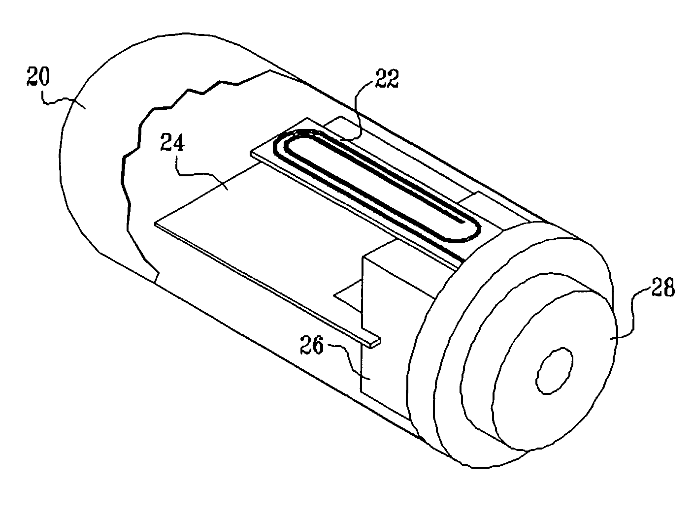
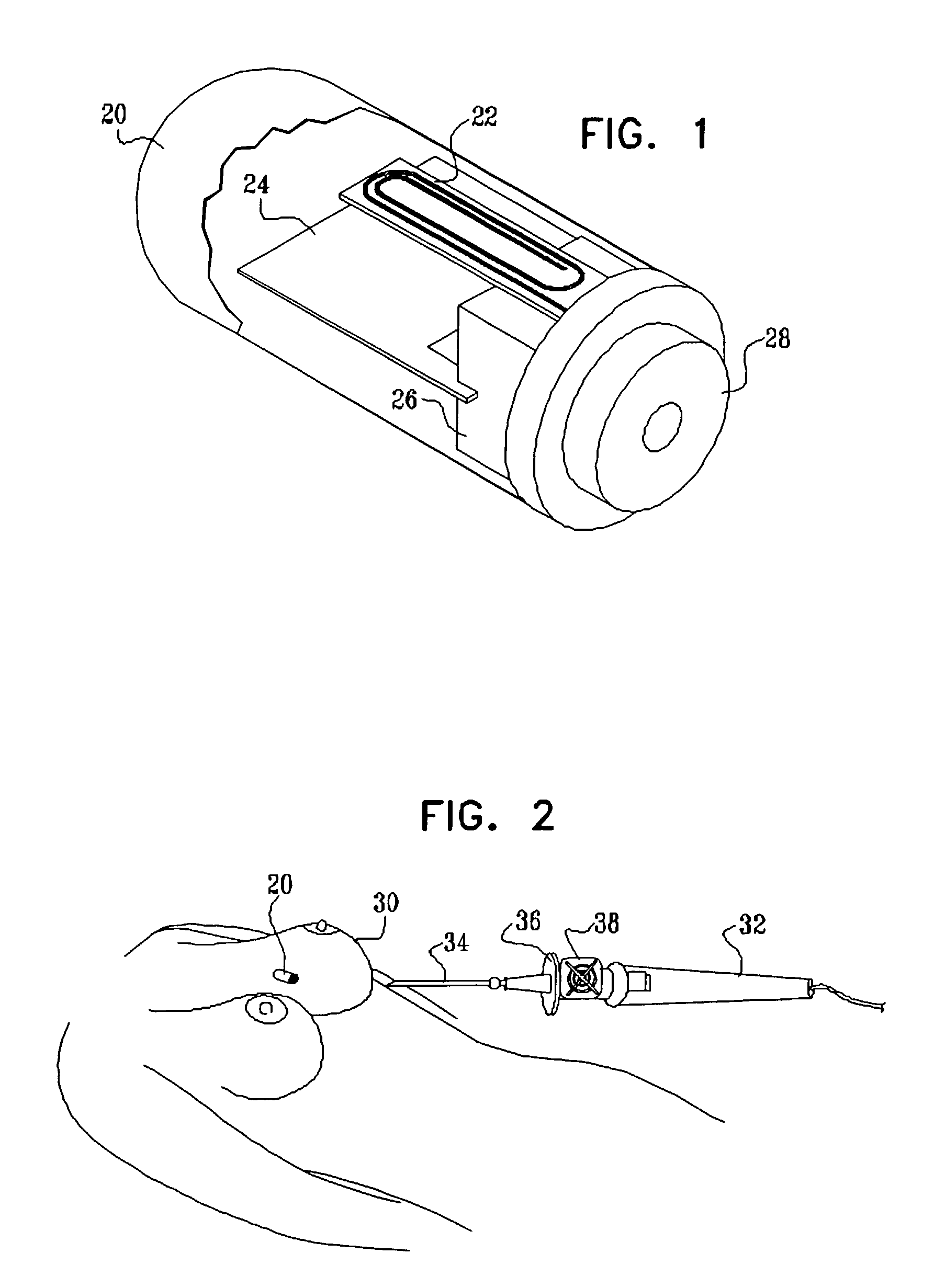
[0049]FIG. 1 is a schematic, pictorial illustration that shows a partly-cutaway view of an implantable passive tag 20, in accordance with a preferred embodiment of the present invention. Tag 20 of the type shown and described here is also referred to herein as a “beacon.” The tag comprises a RF antenna 22, typically having the form of a coil, which is coupled to a capacitor 24 and additional circuitry 26 to define a resonant circuit. The coil, capacitor and circuitry are contained in a sealed, biocompatible package 28, typically made of a plastic or other non-conducting material. In the embodiment pictured in FIG. 1, package 28 includes a base that can be grasped by a radiologist using a suitable inserter tool (not shown in the figures) to position tag 20 at a desired location in soft tissue of a patient.

[0050]Preferably, circuitry 26 comprises a tunnel diode (not shown), such as a 1n3712 diode, which is configured together with antenna 22 and capacitor 24 to form a tunnel diode osc...


PUM


Abstract

Apparatus for locating a tissue within a body of a subject includes an acoustic tag configured to be fixed to the tissue and adapted, responsive to acoustic waves incident thereon, to return acoustic echoes. Acoustic transducers are placed at respective positions so as to direct the acoustic waves into the body toward the tissue and to receive the acoustic echoes returned from the tag responsive to the acoustic waves, generating first signals responsive to the received echoes. Transducer position sensors are coupled respectively to the acoustic transducers so as to generate second signals indicative of the respective positions of the acoustic transducers in an external frame of reference. A processing unit processes the first signals and the second signals so as to determine coordinates of the acoustic tag in the external frame of reference.

Description

CROSS-REFERENCE TO RELATED APPLICATIONS[0001]This application is a continuation-in-part of U.S. patent application Ser. No. 10 / 029,595, filed Dec. 21, 2001, which is a continuation-in-part of U.S. patent application Ser. No. 09 / 265,715, filed Mar. 11, 1999. This application is also related to two other U.S. patent applications, filed on even date, entitled “Position Sensing System with Integral Location Pad and Position Display,” and “Invasive Medical Device with Position Sensing and Display.” All these related applications are incorporated herein by reference.FIELD OF THE INVENTION[0002]The present invention relates generally to systems for determining the position of an object inside a human body, and specifically to the use of such systems in guiding tools and other devices used in medical procedures.BACKGROUND OF THE INVENTION[0003]The use of implanted markers or clips for surgical guidance is known in the art. For example, upon identifying a suspicious lesion in the breast, a r...

Claims


Application Information

Patent Timeline
Patent Type & Authority Patents(United States)
IPC IPC(8): A61B5/05A61B5/06A61B5/07A61B10/00A61B10/02A61B10/04A61B17/00A61B17/11A61B17/34A61B19/00
CPCA61B5/06A61B17/1114A61B17/3403A61B19/52A61B19/5244A61B19/54A61B2019/547A61B10/0233A61B19/56A61B2010/045A61B2017/008A61B2017/3413A61B2019/507A61B2019/5251A61B2019/5263A61B2019/5272A61B2019/5408A61B2019/5425A61B2019/5429A61B2019/5454A61B2019/5458A61B10/0041A61B90/36A61B2034/2063A61B2034/2072A61B34/20A61B34/25A61B2034/107A61B2034/2051A61B90/39A61B2090/3908A61B2090/3925A61B2090/3929A61B2090/3954A61B2090/3958A61B2090/397A61B5/061A61B5/062A61B90/37A61B10/04A61B17/00234A61B2090/3782A61B2090/3987
Inventor GOVARI, ASSAFSCHWARTZ, YITZHACK
Owner BIOSENSE
Why Eureka
Try Eureka