Pressure lamination method for forming composite ePTFE/textile and ePTFE/stent/textile prostheses

a technology of pressure lamination and composite eptfe, which is applied in the direction of prosthesis, blood vessels, surgery, etc., can solve the problems of increasing the thickness of the tubular structure, affecting the implantation process, and affecting the implantation effect of the prosthesis,

Inactive Publication Date: 2009-07-14
LIFESHIELD SCI
View PDF100 Cites 97 Cited by
  • Summary
  • Abstract
  • Description
  • Claims
  • Application Information

AI Technical Summary

Problems solved by technology

While grafts formed in this manner overcome certain disadvantages inherent in attempts to balance porosity and fluid tightness, these textile prostheses may exhibit certain undesirable characteristics.
These characteristics may include an undesirable increase in the thickness of the tubular structure, which makes implantation more difficult.
These textile tubes may also be subject to kinking, bending, twisting or collapsing during handling.
Moreover, application of a coating may render the grafts less desirable to handle from a tactility point of view, and therefore more difficult to implant.
Further such grafts may have a profile not suitable for use as an endovascular device.
Grafts formed of ePTFE tend to be relatively non-compliant as compared with textile grafts and natural vessels.
Further, while exhibiting a high degree of tensile strength, ePTFE grafts are susceptible to tearing.
Additionally, ePTFE grafts lack the suture retention strength of coated textile grafts.
This may cause undesirable bleeding at the suture hole.
Thus, the ePTFE grafts lack many of the advantageous properties of certain textile grafts.
It is also known that it is extremely difficult to join PTFE and ePTFE to other materials via adhesives or bonding agents due to its chemically inert and non-wetting character.
Thus, heretofore, attempts to bond ePTFE to other dissimilar materials, such as textiles, have been difficult.
The use of such a heat-shrinkable sleeve and flowable mass particulate, however, complicated the lamination process.
This makes control of the amount of pressure applied, especially along the length of the stent and the ePTFE layers, difficult, leading to variability of the bonding strength along such lengths.

Method used


Image

  • Pressure lamination method for forming composite ePTFE/textile and ePTFE/stent/textile prostheses
  • Pressure lamination method for forming composite ePTFE/textile and ePTFE/stent/textile prostheses
  • Pressure lamination method for forming composite ePTFE/textile and ePTFE/stent/textile prostheses

Examples


example 1

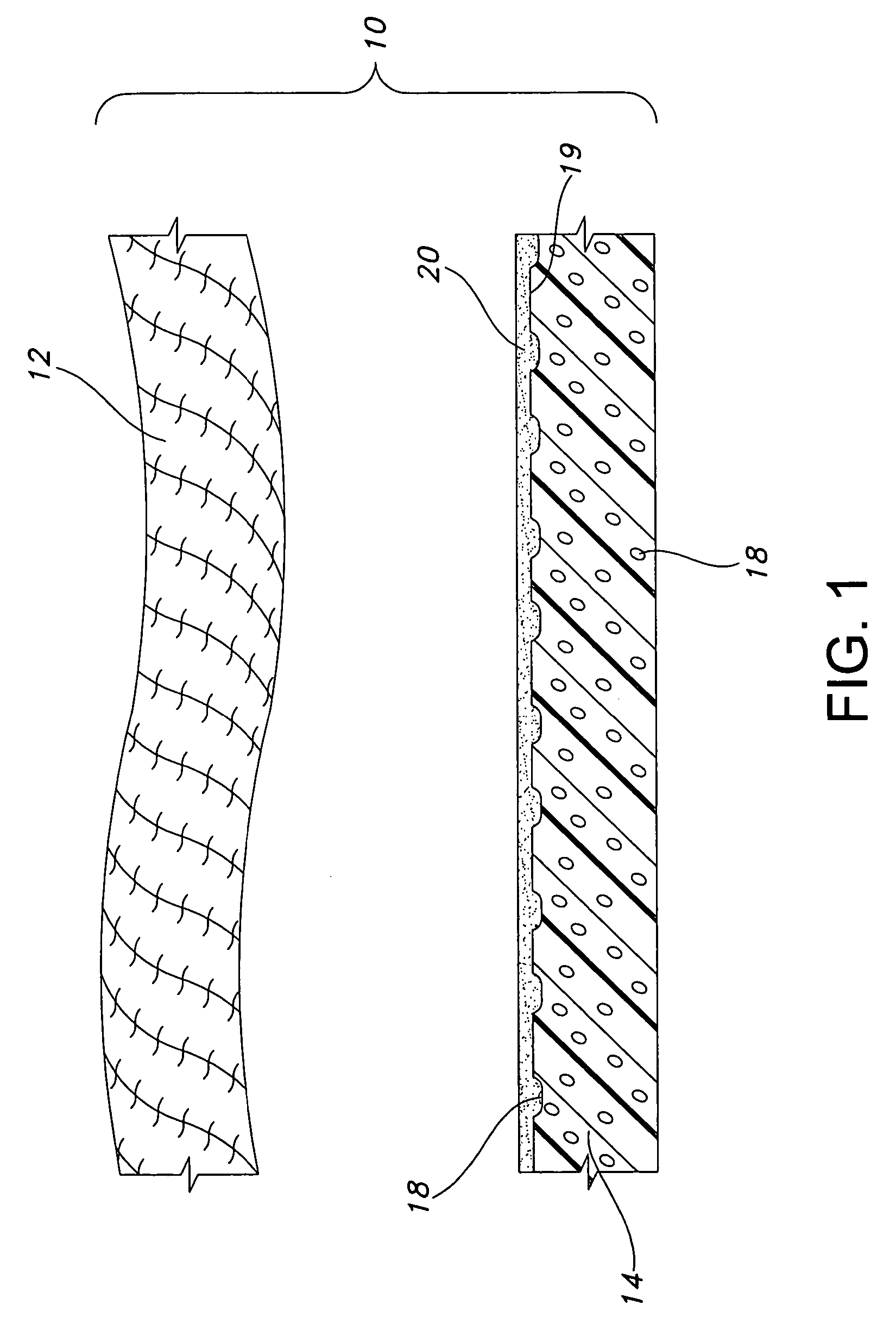
Textile / ePTFE Prosthesis

[0125]Textile and ePTFE prosthesis components were pressured laminated in accordance with the present invention to provide a pressure-laminated prosthesis. The pressure laminated device was compared to a similar device, i.e., a control, prepared without pressure lamination.

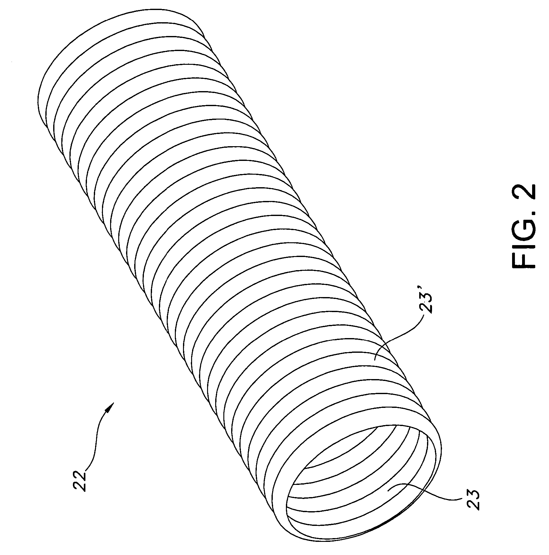
[0126]Single layered textile grafts were prepared by knitting PET yarns in a two-needle underlap and a one-needle overlap to provide a high stretch tubular graft having a nominal internal diameter of about 13 mm. High stretch ePTFE: tubular members having a nominal tubular diameter of about 13 mm were also prepared. The ePTFE tubular members had a wall thickness of about 175 to about 225 microns. Straight or linear ePTFE tubular members or constructs had from about 800 or greater percent longitudinal expansibility. Bifurcated ePTFE tubular members or constructs had from about 2,000 percent or greater longitudinal expansibility. Corethane® was applied as an adhesive bonding agent to secure t...

example 2

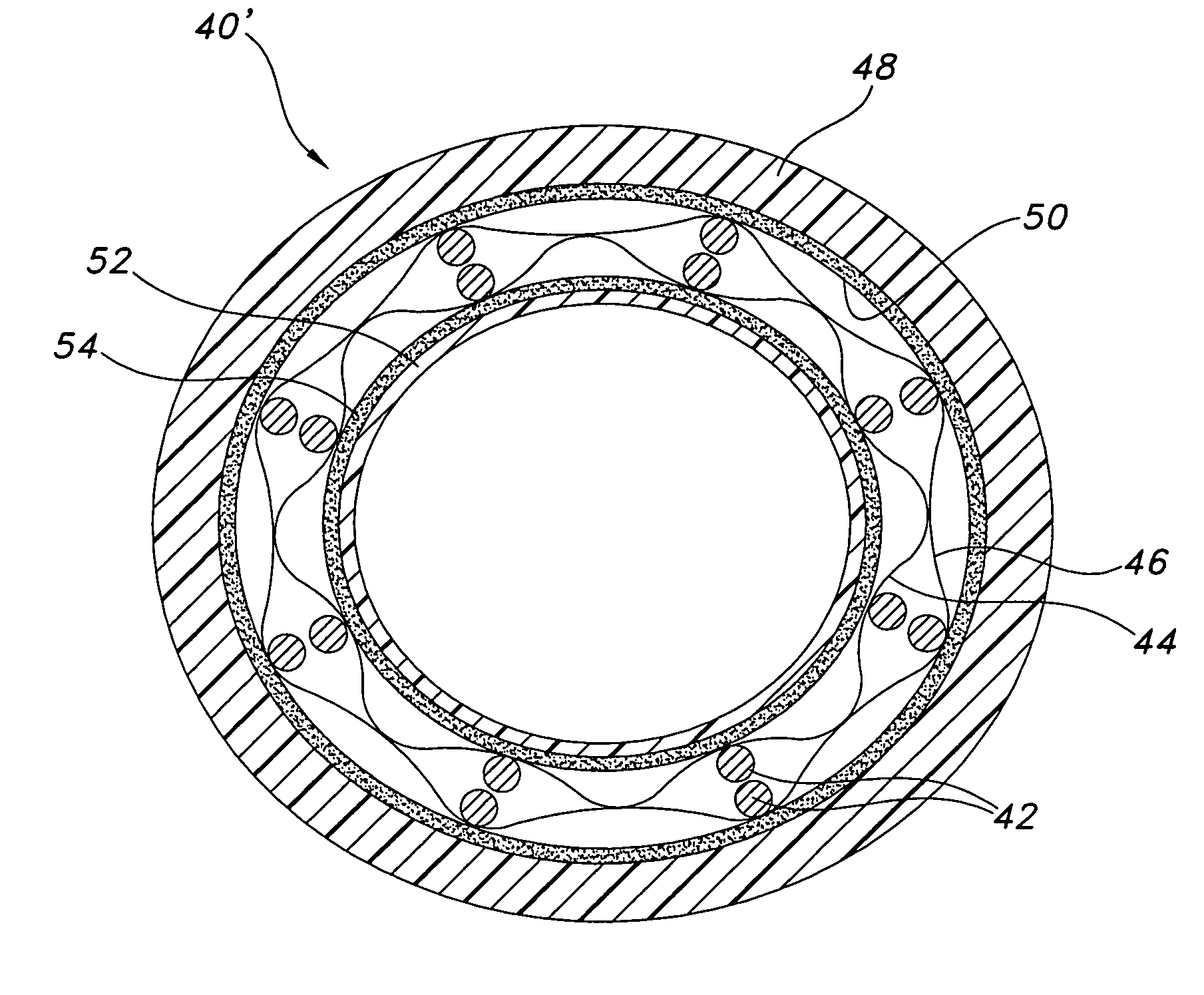
Textile / ePTFE / Stent Prosthesis

[0132]Metal stents (Wallstent®) of about 13 mm in diameter were provided and placed on the above-described 13 mm mandrels. The composite textile / ePTFE prosthesis components from Example 1 were also used as described above (i.e., textile, Corethane® and ePTFE), except that Corethane® was also applied to the stent wires to bond the stent and the ePTFE. Textile, ePTFE and stent prosthesis components were pressured laminated in accordance with the present invention to provide a pressure-laminated prosthesis under the conditions described in Example 1 and a control was also prepared under the conditions described in Example 1.

[0133]The pressure-laminated composite prostheses of the present invention had improved mechanical properties over the control, as detailed below in Table 2.

[0134]

TABLE 2Textile / ePFTE / Stent ProsthesesInventivePressure“Control”LaminatedLaminatedCompositeCompositeMechanical PropertiesDeviceDeviceBond Shear Strength(1)kilograms5.294.30stan...


PUM

PropertyMeasurementUnit
thicknessaaaaaaaaaa
pressureaaaaaaaaaa
temperatureaaaaaaaaaa

Abstract

A method of forming a composite textile and ePTFE implantable device includes the steps of (a) providing an ePTFE layer having opposed surfaces comprising a microporous structure of nodes interconnected by fibrils; (b) providing a textile layer having opposed surfaces; (c) applying a coating of an elastomeric bonding agent to one of the opposed surfaces of the ePTFE layer or the textile layer; (d) providing a hollow member having an open end and an opposed closed end defining a fluid passageway therebetween and having a wall portion with at least one hole extending therethrough, the hole being in fluid communication with the fluid passageway; (e) concentrically placing the ePTFE layer and the textile layer onto the hollow member and over the at least one hole of the hollow member to provide an interior composite layer and an exterior composite layer, thereby defining a composite assembly, wherein the interior composite layer is one of the ePTFE layer or the textile layer and the exterior composite layer is the other of the ePTFE layer or the textile layer; (f) placing the hollow member with the composite assembly within a pressure chamber; (g) applying a pressure differential so that the pressure within the chamber is greater than a pressure within the fluid passageway of the hollow member; and (h) applying heat to the bonding agent to adhesively bond the textile layer and the ePTFE layer to provide a laminated composite assembly.

Description

CROSS-REFERENCE TO RELATED APPLICATIONS[0001]This application is a continuation-in-part of application Ser. No. 10 / 167,676, filed Jun. 11, 2002, now abandoned which claims the benefit of Provisional Application No. 60 / 279,401, filed Jun. 11, 2001, and is also a continuation-in-part of application Ser. No. 10 / 166,842, filed Jun. 11, 2002, the contents all of which are incorporated herein by reference.FIELD OF THE INVENTION[0002]The present invention relates generally to an implantable prosthesis. More particularly, the present invention relates to a pressure lamination method for providing a composite multilayer implantable structure having a textile layer, an expanded polytetrafluoroethylene layer (ePTFE) and an elastomeric bonding agent layer or a heat or a pressure sensitive adhesive layer, preferably elastomeric, within the ePTFE porous layer, which joins the textile and ePTFE layer to form an integral structure.BACKGROUND OF THE INVENTION[0003]Implantable prostheses are commonly...

Claims


Application Information

Patent Timeline
Patent Type & Authority Patents(United States)
IPC IPC(8): B32B37/00B32B37/10A61F2/00A61F2/06A61L27/16A61L27/48A61L31/04A61L31/12
CPCA61F2/06A61F2/07A61L27/16A61L27/507A61L31/048A61L31/129A61L27/48C08L27/18A61F2002/072A61F2/89
Inventor RAKOS, RONALDSOWINSKI, KRZYSZTOF
Owner LIFESHIELD SCI
Why Eureka
Try Eureka