Biased-MOSFET active bridge

a technology of active bridge and mosfet, which is applied in the direction of reverse polarity correction, safety/protection circuit, power conversion system, etc., can solve the problems of significant variable voltage drop across the battery reversal circuit, equipment damage, and equipment damag

Inactive Publication Date: 2009-07-14
HARRIS CORP
View PDF15 Cites 27 Cited by
  • Summary
  • Abstract
  • Description
  • Claims
  • Application Information

AI Technical Summary

Benefits of technology

[0011]Applying voltage to the active bridge circuit will cause current to flow through the forward biased body diodes of the field effect transistors. This current generates a voltage at the bias voltage tap when it flows through the voltage divider circuit. The voltage derived from the bias voltage tap is used for biasing each transistor to an “on” state in which current can flow between the drain and source. Turning on the field effect transistor shorts the body diode, leaving only a small resistance between the drain and source as current flows through a conductive channel formed by the transistor. The voltage divider circuit also ensures that the voltage between the gate and the source is reduced relative to the input voltage. This ensures operation of the transistor active bridge circuit over a wider range of input voltages without risk of damage to the transistors. In this regard, the transistor active bridge circuit can also include a zener diode connected between the gate and the source of each respective one of the field-effect transistors. The zener diode can be provided to serve as a further means for ensuring that the voltage between the gate and source terminals is limited.

Problems solved by technology

Although batteries are generally not difficult to replace, there is at least one potential installation error that can cause serious damage to equipment.
Such an occurrence can prevent a system from operating and may cause damage to the equipment.
For example, the semiconductors used in bipolar devices can result in a significant variable voltage drop across the battery reversal circuit.
This can be a problem for low power systems where low voltage drop and low power loss is desirable.
Despite the advantages offered by such MOSFET circuits that allow devices to operate with battery polarity reversed, they still suffer from certain drawbacks.
This is due to the fact that for most MOSFET devices, the maximum voltage that can be applied between the gate and the source is rather limited.
Gate to source voltages that exceed a specified value Vgs—max can damage the MOSFET components.
This can be a problem with existing designs because practically the full value of the battery voltage will be applied across the gate to source terminals of the MOSFET.

Method used


Image

  • Biased-MOSFET active bridge
  • Biased-MOSFET active bridge
  • Biased-MOSFET active bridge

Examples


Embodiment Construction

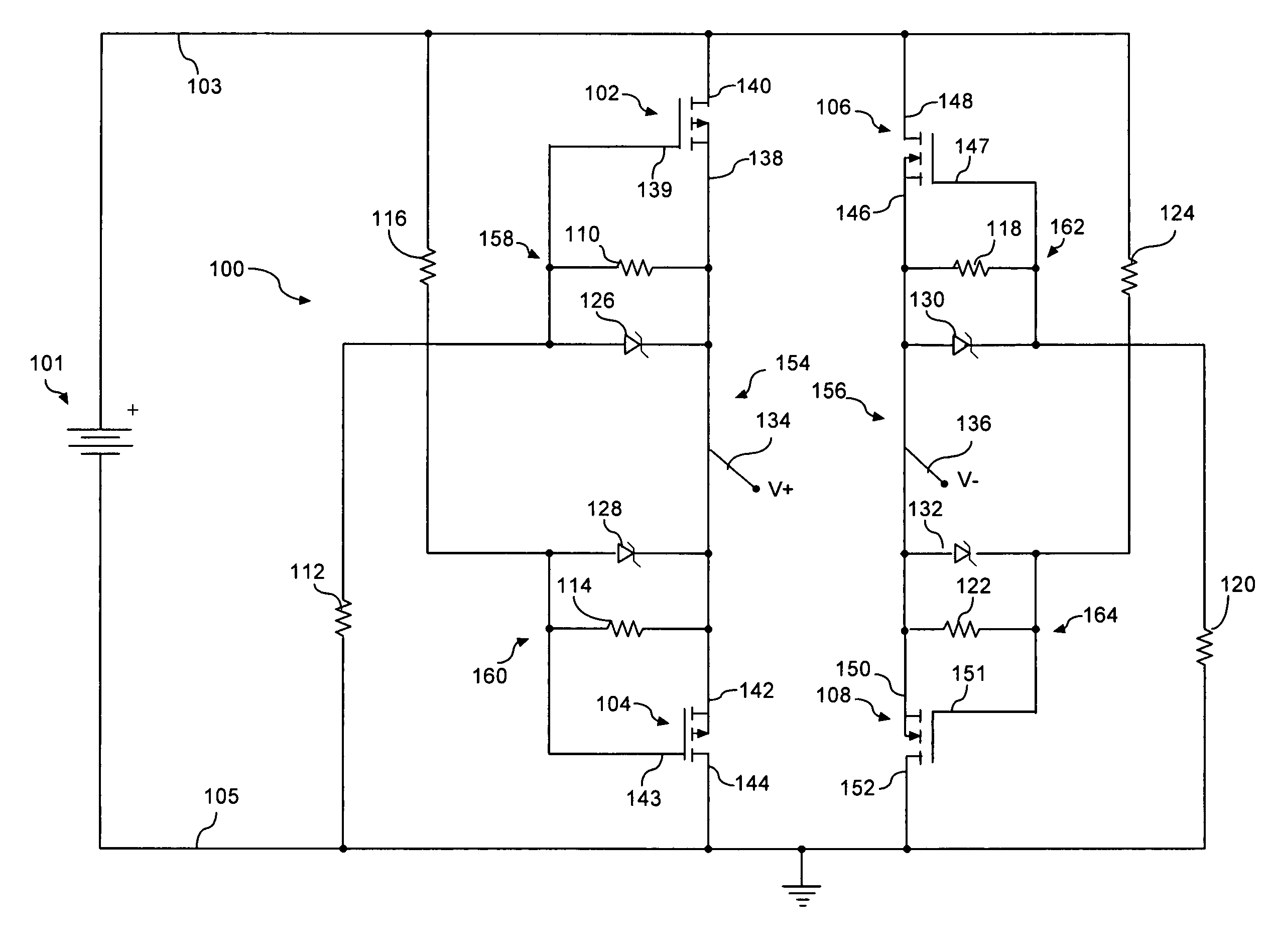
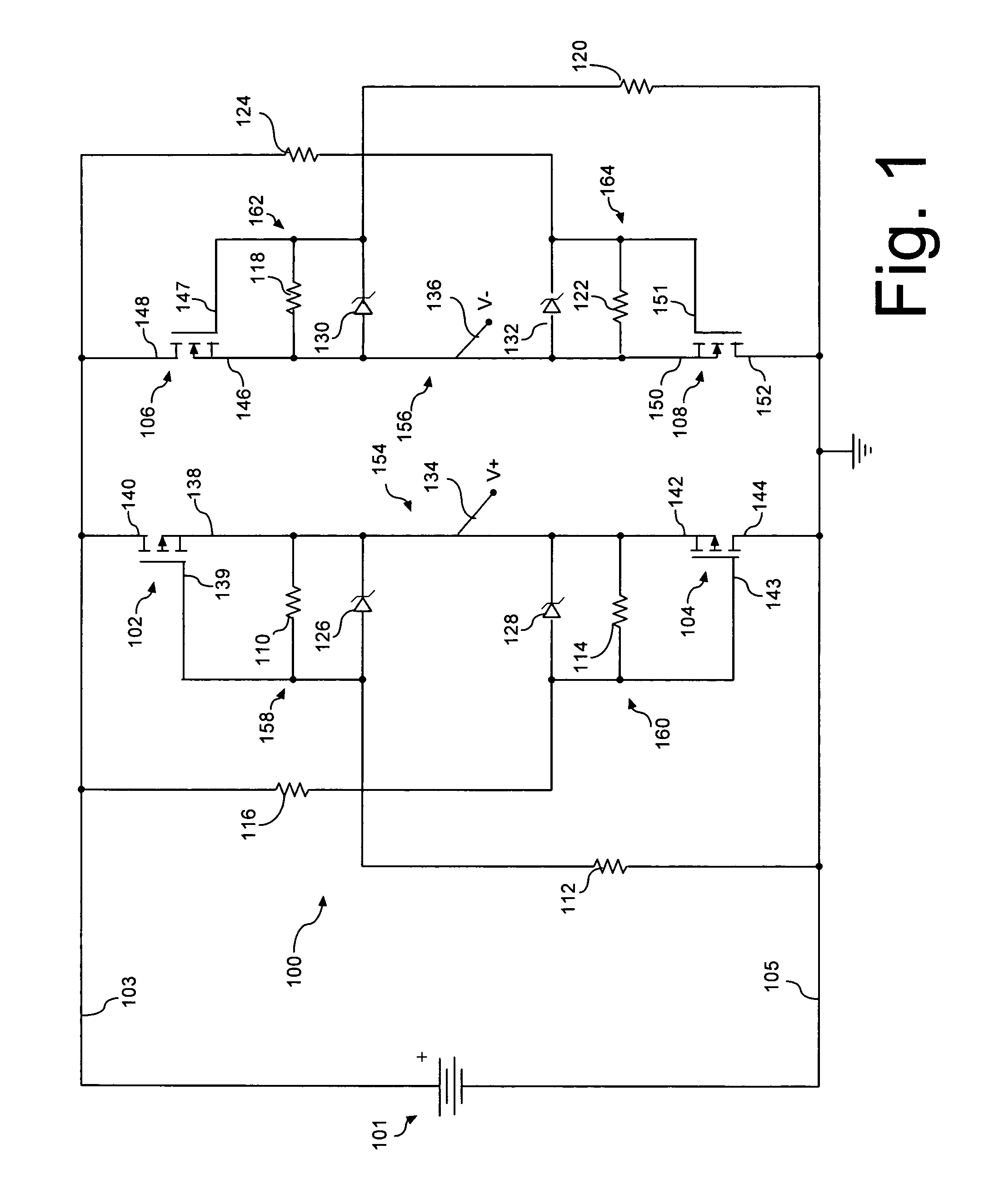
[0015]A transistor active bridge circuit 100 is shown in FIG. 1. The circuit 100 shown is useful for a variety of purposes, including operating and protecting devices in the event of a battery polarity reversal. As may be observed in FIG. 1, circuit 100 is connectable between a pair of input lines 103, 105 and a pair of output lines 134, 136 to ensure that a load receives a proper polarity voltage regardless of whether a power source 101 provided for powering a load (not shown) is properly installed.

[0016]Circuit 100 includes first and second field-effect transistors 102, 104 of a first channel type. The transistor active bridge circuit also includes third and fourth field-effect transistors 106, 108 of a second channel type that is different from the first channel type. For example, the first and second field effect transistors 102, 104 can be P-channel type whereas the third and fourth field effect transistors 106, 108 can be N-channel type. According to an embodiment of the inven...


PUM


Abstract

A transistor active bridge circuit (100) provides operation and protection for devices from the effects of battery polarity reversal. The circuit includes first and second field-effect transistors (102, 104) of a first channel type, and third and fourth field-effect transistors (106, 108) of a second channel type that is different from the first channel type. A set of voltage dividers (110, 112, 114, 116, 118, 120, 122, 124) and voltage clamping devices (126, 128, 130, 132) permit the circuit (100) to efficiently operate over a wider range of input voltages, without potential damage to the field-effect transistors.

Description

STATEMENT REGARDING FEDERALLY SPONSORED RESEARCH OR DEVELOPMENT[0001]This invention was constructed on Government Contract No. PA180C. The government has certain rights in the invention.BACKGROUND OF THE INVENTION[0002]1. Statement of the Technical Field[0003]The inventive arrangements relate to MOSFET circuits, and more particularly to a circuit for battery reversal operation and protection.[0004]2. Description of the Related Art[0005]Batteries are used as power sources in a wide variety of devices. Typically, these batteries are designed for user replacement. Although batteries are generally not difficult to replace, there is at least one potential installation error that can cause serious damage to equipment. Specifically, installation of a battery with the polarity reversed. This situation occurs when the positive terminal of the battery is connected to the negative power terminal of the equipment, and the negative terminal is connected to the positive power terminal of the devi...

Claims


Application Information

Patent Timeline
Patent Type & Authority Patents(United States)
IPC IPC(8): H02H11/00
CPCH02J7/0034
Inventor SELLS, TROY WOODROW
Owner HARRIS CORP
Why Eureka
Try Eureka