Work machine

a work machine and pump motor technology, applied in the field of work machines, can solve the problems of inability to apply, limited application of pump motor and motor generator combination, and difficulty in controlling the plurality of supporting circuits, so as to ensure the stability of the boom cylinder, prevent the occurrence of shock, and increase the flow rate proportion of fluid

Inactive Publication Date: 2009-07-21
CATEPILLAR SARL
View PDF7 Cites 23 Cited by
  • Summary
  • Abstract
  • Description
  • Claims
  • Application Information

AI Technical Summary

Benefits of technology

[0016]According to the present invention, the boom control circuit, which includes the boom pump provided separately from the main pump of the hybrid type drive system and serves to control hydraulic fluid fed from the boom pump to the boom cylinder, is adapted to function independently of the travel / stick / bucket control circuit, which serves to control hydraulic fluid fed from the main pump of the hybrid type drive system to the travel motor, the stick cylinder, and the bucket cylinder. Therefore, the flow rate required by the boom cylinder can be easily ensured by, for example, controlling the rotation speed of the boom pump by means of the boom motor generator without being affected by the hydraulic fluid fed to the travel motor, the stick cylinder, or the bucket cylinder. Furthermore, the boom control circuit is capable of disengaging the clutch so that the energy recovery motor driven by return fluid discharged from the boom cylinder efficiently inputs driving power to the boom motor generator, which is under no-load condition, and that the generated electric power is stored in the electric power storage device. The boom control circuit is also capable of engaging the clutch so that electric power fed from the electric power storage device enables the boom motor generator to function as an electric motor to drive the boom pump, thereby feeding hydraulic fluid from the boom pump to the boom cylinder. Thus, energy of return fluid discharged from the boom cylinder can be effectively recovered even in an open circuit.
[0017]According to another embodiment of the present invention, when controlling hydraulic fluid fed from the main pump of the hybrid type drive system to the travel motor, the boom cylinder, the stick cylinder, and the bucket cylinder, the hydraulic actuator control circuit enables the energy recovery motor driven by return fluid discharged from the boom cylinder to input driving power to the boom motor generator so that the generated electric power is stored in the electric power storage device of the hybrid type drive system. The hydraulic actuator control circuit also enables the boom motor generator to be driven by electric power fed from the electric power storage device of the hybrid type drive system so that the boom motor generator functions as an electric motor to drive the boom assist pump, thereby feeding hydraulic fluid from the boom assist pump to the boom cylinder. Thus, energy of return fluid discharged from the boom cylinder can be effectively recovered even in an open circuit.
[0019]According to an embodiment of the present invention, the energy recovery motor is provided in one of the return passages through which return fluid discharged from the boom cylinder flows, and the flow rate ratio control valve controls a flow rate ratio of a flow rate of the return fluid passing through the energy recovery motor and a flow rate of the return fluid in the other return passage, which branches off the first mentioned return passage at a location upstream of the energy recovery motor. Therefore, the configuration according to the present invention is capable of gradually increasing the flow rate proportion of the fluid distributed towards the energy recovery motor from the moment when return fluid starts to flow from the boom cylinder, thereby preventing occurrence of shock, as well as ensuring stable function of the boom cylinder by preventing a sudden change in load to the boom cylinder.
[0020]According to the present invention disengaging the clutch enables the energy recovery motor, which is driven by return fluid discharged from the boom cylinder, to efficiently input driving power to the boom motor generator, which is under no-load condition, so that the generated electric power is stored in the electric power storage device of the hybrid type drive system. When the clutch is engaged, electric power fed from the electric power storage device of the hybrid type drive system enables the boom motor generator to function as an electric motor to drive the boom assist pump, thereby feeding hydraulic fluid from the boom assist pump to the boom cylinder.
[0021]According to another embodiment of the present invention, the solenoid valve between bucket and boom is disposed in the boom cylinder hydraulic fluid feeding passage. Therefore, by opening this solenoid valve, a combined amount of hydraulic fluid can be fed from one of the main pumps and the boom assist pump to the boom cylinder. Therefore, it is possible to increase the speed of boom raising action by the boom cylinder and improve working efficiency. Furthermore, a high pressure to the bucket cylinder can be ensured by closing the solenoid valve. As the solenoid valve between bucket and stick is disposed in the circuit-to-circuit communicating passage between bucket and stick, opening this solenoid valve ensures supply of hydraulic fluid from another main pump to the stick cylinder, thereby increasing the speed of action of the stick cylinder and improving working efficiency. Furthermore, a high pressure to the bucket cylinder can be ensured by closing the solenoid valve.
[0022]According to the present invention, the solenoid valve between stick and boom is disposed in the circuit-to-circuit communicating passage between stick and boom for providing fluid communication between the stick cylinder hydraulic fluid feeding passage and the head-side of the boom cylinder. Therefore, by opening this solenoid valve, hydraulic fluid can be fed to the head-side of the boom cylinder not only from the first-mentioned main pump and the boom assist pump but also from the second-mentioned main pump, thereby increasing the speed of boom raising action by the boom cylinder and improving working efficiency. Furthermore, supply of hydraulic fluid to the stick cylinder can be ensured by closing the solenoid valve.

Problems solved by technology

Therefore, it is difficult to control the plurality of supporting circuits so that they satisfy these requirements.
Furthermore, the aforementioned combination of the pump motor and the motor generator is limited to a closed circuit and cannot be applied to an open circuit that serves to direct return fluid discharged from hydraulic actuators back to a tank.

Method used


Image

  • Work machine
  • Work machine
  • Work machine

Examples


Embodiment Construction

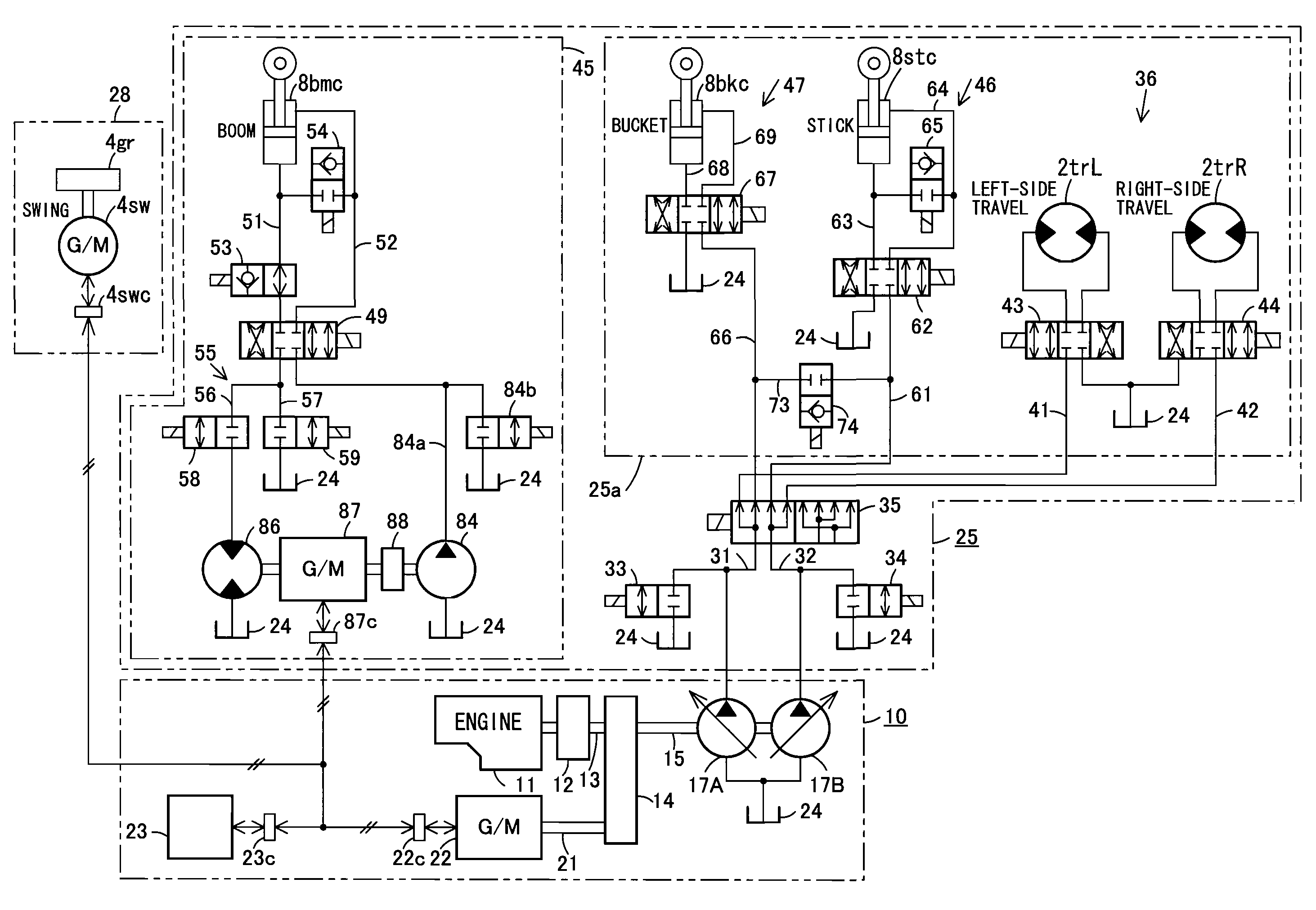
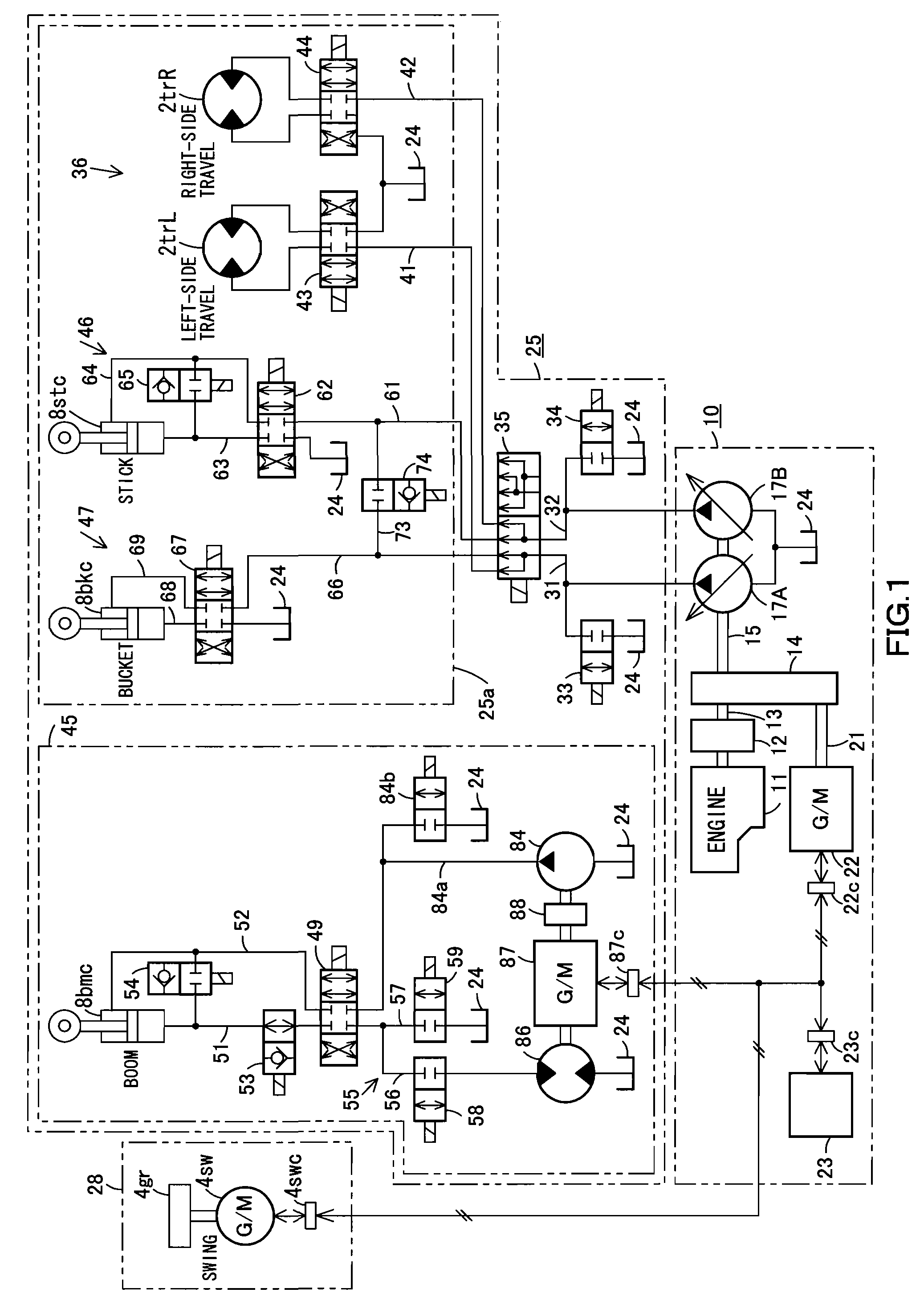
[0026]Next, the present invention is explained in detail hereunder, referring to an embodiment thereof shown in FIGS. 1 and 2 and another embodiment shown in FIG. 3. The fluid and fluid pressure used in those embodiments are hydraulic oil and oil pressure, respectively.

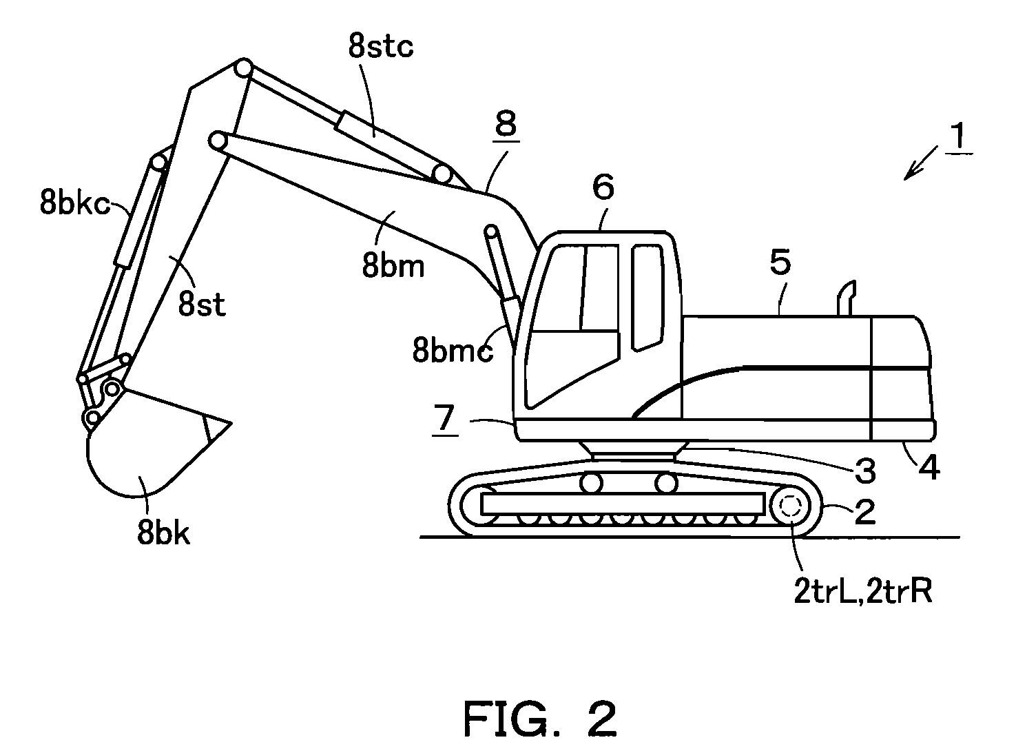
[0027]First, the embodiment shown in FIGS. 1 and 2 is explained. As shown in FIG. 2, a work machine 1 is a hydraulic excavator that includes a machine body 7. The machine body 7 is comprised of a lower structure 2, an upper structure 4 rotatably mounted on the lower structure 2 with a swing bearing portion 3 therebetween, and components mounted on the upper structure 4. The components mounted on the upper structure 4 include a power unit 5 comprised of an engine, hydraulic pumps, etc., and a cab 6 for protecting an operator. The lower structure 2 is provided with travel motors 2trL,2trR for respectively driving right and left crawler belts. The upper structure 4 is provided with a swing motor generator (not shown in F...


PUM


Abstract

A boom control circuit for controlling hydraulic fluid fed to a boom cylinder is provided separately and independently from a travel / stick / bucket control circuit, which serves to control hydraulic fluid fed to travel motors, a stick cylinder, and a bucket cylinder. The boom control circuit includes a boom pump, an energy recovery motor disposed in a return passage through which return fluid from the boom cylinder 8bmc passes, and a boom motor generator connected to the energy recovery motor. The aforementioned boom pump is connected through a clutch to the boom motor generator. The invention is capable of providing a work machine of which a boom control circuit is adapted to function independently so that the flow rate required by the boom control circuit can be easily ensured.

Description

CROSS REFERENCE TO PRIOR APPLICATION[0001]This is a U.S. national phase application under 35 U.S.C. § 371 of International Patent Application No. PCT / JP2006 / 307532 filed Apr. 10, 2006 and claims the benefit of Japanese Application No. 2005-162511 filed Jun. 2, 2005 and Japanese Application No. 2005-162512 filed Jun. 2, 2005, all of which are incorporated by reference herein. The International Application was published in Japanese on Dec. 7, 2006 as International Publication No. WO 2006 / 129422 under PCT Article 21(2).TECHNICAL FIELD[0002]The present invention relates to a work machine provided with a hybrid type drive device.BACKGROUND ART[0003]A driving system for a work machine, such as a hydraulic excavator, may include a hybrid type drive system that has an electric generator, which is adapted to be driven by an engine, and an electric power storage device for storing electric power generated by the generator. An electric motor or a motor generator is operated by power supplied f...

Claims


Application Information

Patent Timeline
Patent Type & Authority Patents(United States)
IPC IPC(8): E02F5/02F16D31/02
CPCE02F9/2075E02F9/2292E02F9/2296F15B11/17F15B21/14E02F9/2217F15B2211/88F15B2211/20515F15B2211/20523F15B2211/20538F15B2211/20546F15B2211/20576F15B2211/3111F15B2211/327F15B2211/63F15B2211/7053F15B2211/7058
Inventor TOZAWA, SHOJIBINNAKA, MADOKAFURUTA, HIDETO
Owner CATEPILLAR SARL
Why Eureka
Try Eureka