Composite steel joist/composite beam floor system and steel stud wall systems

a technology of composite beams and floor systems, applied in the direction of load-supporting elements, structural elements, building components, etc., can solve the problems of eccentric loading, significant reduction of the load carrying capacity of bearing walls, and the inability to meet the requirements of light gauge steel stud walls, so as to improve the resistance to vehicular impacts

Inactive Publication Date: 2009-07-21
SIU WILFRED WING CHOW
View PDF38 Cites 33 Cited by
  • Summary
  • Abstract
  • Description
  • Claims
  • Application Information

AI Technical Summary

Benefits of technology

[0047]2. To provide a continuous reinforced concrete beam around the perimeter, and under load-bearing walls and demising walls for added strength and rigidity and increased inter-floor and inter-suite sound and fire separation;
[0060]With the new impact-resistant Perimeter Stud Wall System, the objective of the invention is to provide an economical in-wall concrete wheel-stop along the perimeter of the building to provide improved resistance to vehicular impacts.

Problems solved by technology

This very premise, however, creates eccentricity in the loading, and significantly reduces the load carrying capacity of the bearing wall.
When deep floor assemblies incorporating deep profiled composite decks and / or OWSJ are used, the concept of eccentric loading to a light gauge steel stud wall will prove almost impossible.
Structurally, it adds dead load to the wall, and consequently, increases loading to the lintels over window and door openings in the wall below.
While continuity of the concrete in the floor assembly is maintained within the plane of the load-bearing walls to maintain continuous inter-floor fire and acoustic separation across the bearing walls, there is not enough depth of concrete for any structural use.
To sum up, both Luedtke and de Quesada incorporate metal devices projecting beyond the plane of load-bearing walls to carry the floor assemblies, with resulting eccentricity in loading for the load-bearing walls.
In normal “concrete-topped steel deck on OWSJ” floor construction, the cover concrete thickness (the concrete above the top of the steel deck) is only about 65 mm (2.5 inches), severely limiting the effectiveness of the shear stud connectors.
Consequently, a large number of shear connectors on long girder extensions are required for effective composite action, reducing the cost efficiency of the system.

Method used


Image

  • Composite steel joist/composite beam floor system and steel stud wall systems
  • Composite steel joist/composite beam floor system and steel stud wall systems
  • Composite steel joist/composite beam floor system and steel stud wall systems

Examples


embodiment 1

for OWSJ

[0097]The first level of a load-bearing wall structure is the conventional load-bearing wall, with light gauge steel studs placed between top and bottom tracks.

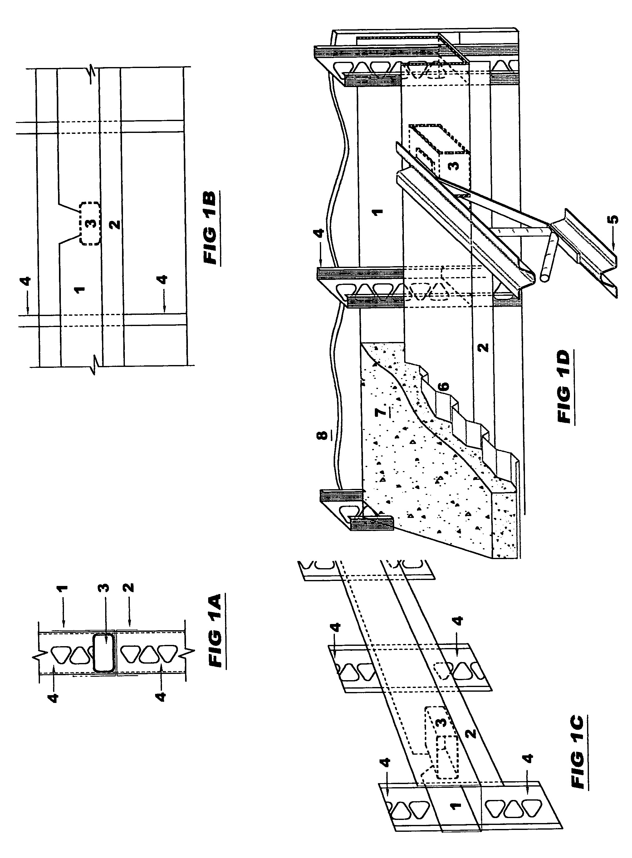
[0098]Each wall panel above the lowest level, illustrated in FIGS. 1A, 1B, and 1C, comprises:[0099]Light gauge steel track, 100 mm deep×width of the wall studs (2);[0100]Light gauge steel studs, with or without perforations along the length, but with at least one perforation in the web at specified location at the bottom (4);[0101]Special bottom track, with cutouts on the inside at specified locations for OWSJ and the exterior leg extending 100 mm above top of OWSJ for concrete closure (1);[0102]Load-bearing block (150×100 tube section shown) at cutout locations (3).

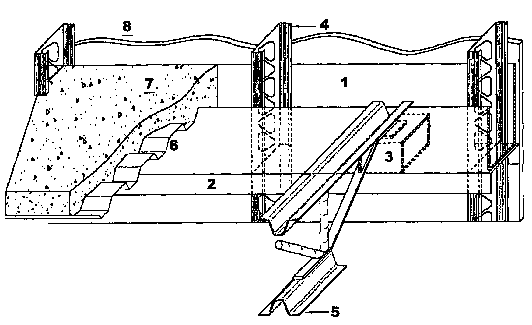
[0103]FIG. 1D illustrates how Embodiment 1 is used for the support of “concrete-topped steel deck on OWSJ” floor system. OWSJ (5) is placed on the load-bearing block (3) through the cutout in the bottom track (1). Steel deck (6) is installed on the OWSJ, b...

embodiment 2

for OWSJ

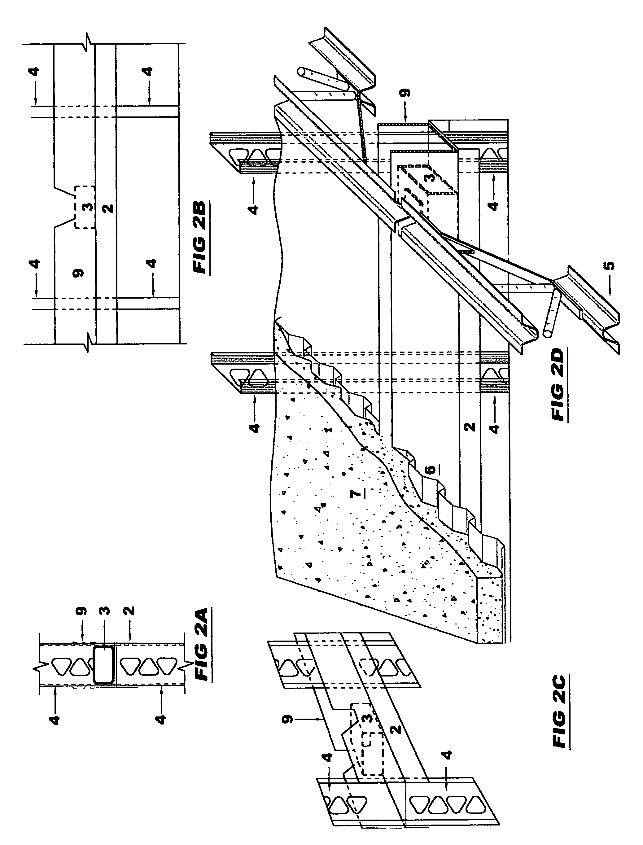
[0104]Embodiment 1 is modified for application in an interior load-bearing wall supporting OWSJ's from both sides. The modification is achieved by having cutouts in both vertical legs of the bottom track (9), and having both vertical legs the same height.

[0105]FIG. 2D illustrates how Embodiment 2 is used for the support of “concrete-topped steel deck on OWSJ” floor system. OWSJ (5) is placed on the load-bearing block (3) through the cutout in the bottom track (9). Steel deck (6) is installed on the OWSJ, but stopped on the both faces of the interior wall. Reinforcing bar(s) is(are) placed in the bottom track. Number and size of reinforcing bars are governed by specific project requirements: OWSJ span, floor loading, window and / or door opening size, etc. Floor concrete can be scheduled after the building is enclosed, and is allowed to flow into the bottom track, forming a reinforced concrete beam inside the wall.

embodiment 3

-profiled Composite Deck

[0106]The first level of a load-bearing wall structure is the conventional load-bearing wall, with light gauge steel studs placed between top and bottom tracks.

[0107]Each wall panel above the lowest level, illustrated in FIGS. 3A, 3B, and 3C, comprises:[0108]Light gauge steel track, 100 mm deep×width of the wall studs (2);[0109]Light gauge steel studs, with or without perforations along the length, but with at least one perforation in the web at specified location at the bottom (1);[0110]Special bottom track, with cutouts at the bottom at locations matching the flutes of the deep-profiled composite deck and the exterior leg above top of the deep-profiled composite deck for concrete closure (10);

[0111]FIG. 3D illustrates how Embodiment 3 is used for the support of concrete-topped deep-profiled composite deck floor system. The deep-profiled composite deck (11) bears on top of the load-bearing wall below. Closure panels (12) are fitted to the deep-profile metal ...


PUM


Abstract

This invention reveals new metal stud perimeter wall and load-bearing wall systems that support, without eccentricity, concrete-topped floors on open-web-steel-joists, deep-profiled composite metal decks and channel-shaped joists and allow upper floor framing to complete before floor concreting; a new composite steel beam for open-web-steel-joist support; a new shear-connection-ready open-web-steel joist; and a new perimeter metal stud wall system that incorporates an in-wall wheel-stopper. The new wall systems incorporate web-perforated studs, and / or web-perforated tracks doubling as concrete closures, and other concrete closure devices. The composite beam incorporates shear connectors protruding through a special web-perforated track fitted with a load-bearing block and cutouts in the legs for open-web-steel-joist support. Unlike composite open-web-steel joists supporting simple-span metal decks, the new shear-connection-ready joist incorporates a flat-topped chord to allow continuous steel deck layout and field-installed shear connectors. The new joists are best used with medium-depth wide-fluted composite floor deck for maximum system efficiency.

Description

REFERENCE TO SEQUENCE LISTING, A TABLE, OR A COMPUTER PROGRAM LISTING COMPACT DISC APPENDIX[0001]Not ApplicableBACKGROUND OF THE INVENTION[0002]Load-Bearing Wall Construction[0003]In conventional construction of multi-storey structures comprising load-bearing walls, platform framing technique is used. As the name suggests, platform framing relies on the floor assembly to provide a platform for subsequent framing construction. The lower floor supporting elements, usually the load-bearing walls, are constructed, then the floor elements installed, directly bearing on the supporting elements below. The follow-up bearing walls are then constructed, followed by the next upper floor assembly. The process repeats itself until the roof elements are installed. All modern floor systems involve the use of concrete as an integral part of the floor assembly. The fact that subsequent floor construction follows the completion of the floor assembly below means a significant delay in waiting for the ...

Claims


Application Information

Patent Timeline
Patent Type & Authority Patents(United States)
IPC IPC(8): E04H12/02
CPCE04B1/24E04B5/10E04B5/40E04C5/065E04C3/083E04C5/0645E04B2001/2484E04B2001/2481
Inventor SIU, WILFRED WING-CHOW
Owner SIU WILFRED WING CHOW
Why Eureka
Try Eureka