Modular patient support system

a patient support system and modular technology, applied in the field of medicine, can solve the problems of increasing the patient's risk of deep vein thrombosis, pulmonary embolism and pneumonia, and the entanglement of myriad devices, and achieve the effects of reducing pneumonia, and increasing the risk of pulmonary embolism

Active Publication Date: 2009-07-21
LIVENGOOD ENG
View PDF73 Cites 37 Cited by
  • Summary
  • Abstract
  • Description
  • Claims
  • Application Information

AI Technical Summary

Benefits of technology

[0013]The present invention solves the above-mentioned deficiencies by providing a mobile cart or platform that is structurally stable, and can thereby provide weight-bearing assistance to a patient without being predisposed to tipping over. In addition, the platform preferably includes one or more additional features, such as an oxygen source, power supply, injection pump, suction pump, body fluid collection devices, vital monitoring equipment, integrated IV pole and communication equipment.
[0014]In accordance with embodiments of the present invention, a modular patient support system is provided, wherein the support system typically resembles a platform, and includes a handrail interconnected to a base having three or more wheels. The support system or platform additionally may include a battery or uninterruptible power supply for serving as an emergency power supply, and / or for powering associated equipment, including the bed, while the patient is walking or being moved in a bed with the support system positioned adjacent the bed. The support platform also may include modular receptacles for receiving a variety of devices, including suction pumps, injection pumps, collection devices, monitoring equipment, and communication devices. An electrical wiring network may be provided such that the modular devices interconnected to the support platform receive electrical power directly at the modular receptacles, thereby minimizing the presence of numerous power cords. Such additional equipment is powered by the uninterruptible power supply when the support platform is disengaged from a stationary power supply, such as an electrical wall outlet.
[0019]In a separate aspect of the invention, an attachment device is provided for detachably attaching the support platform to another structure, such as the patient's bed. The attachment device may include an attachment adapter capable of being interconnected to a variety of bed frame structures, regardless of whether the framing includes square or round rails or posts. The attachment device not only secures the support platform to the bed so that it is not moved when accidentally bumped, but it also enables the support platform to be moved with the bed without the need for a separate attendant to move the support platform. In at least one embodiment, a plurality of bed hooks are used to enable the platform to grasp another object, such as a bed, when the bed is raised to impinge upon the underside of the bed hooks.

Problems solved by technology

Such devices often create a hazard for the patient both directly and indirectly.
The myriad of devices may become entangled and inadvertently removed if not adequately accounted for by the patient or caregiver.
The patients thus do not get out of bed and ambulate as often since the staff of the typical health facility is not able to provide this kind of support readily to all of the patients at all times.
The resulting immobility increases the patient's risk for deep venous thrombosis, pulmonary embolus and pneumonia.
The patient-care staff is also at risk for injury, as they must provide physical support to the debilitated patient.
Back injuries are frequent in healthcare staff as a result of the physical nature of assistance provided.
However, typical IV poles are approximately 6 to 7 feet tall, and are often unstable for providing weight support to a patient, particularly when one or more substantially full IV bags are positioned near the top of the pole.
As a result, a patient is at risk of further injury by falling if the IV pole tips and / or falls over.
In addition, in order to prevent tipping, conventional IV poles have widely spread wheels, which require a large amount of floor space.
IV poles are completely unable to manage uneven terrain as is found outside the confines of the patient care facility, and as may be found at home or in the field for disasters or military operations.
In addition to being relatively unstable, current IV poles do not provide for the additional needs of a patient that is moving about.
Current IV poles also do not include various pumps or suction devices that may be necessary for continuous operation to provide proper medical treatment to the patient.
Furthermore, even if an IV pole is adapted to include a monitoring device or pump, the IV pole tends to become even more unstable because the resulting added weight of the device typically is positioned relatively high along the pole.
However, because use of a walker usually requires both hands of the patient, a patient is typically unable to take an IV pole with them when using a walker.
A further difficulty exists when a patient needs to be moved from one room to another while in their bed.
This can create difficulties depending upon the size of the bed and the patient.
Additionally, portable suction and vitals monitoring are not readily available for every patient.
Eliminating this move prevents an opportunity for a patient fall resulting in injury with only a single staff member assisting.
Patient care devices and services such as suction and oxygen are not built in to the facilities of several countries and regions.
Yet a further difficulty exists in maintaining electrical power to electronic devices such as monitoring equipment, suction pumps and / or injection pumps while the patient is walking with an IV pole or walker, or while the patient is being moved in their bed or while the patient is not located next to an electrical outlet.

Method used


Image

  • Modular patient support system
  • Modular patient support system
  • Modular patient support system

Examples


Embodiment Construction

[0075]In accordance with embodiments of the present invention, a platform is provided that has application for use in a variety of fields, one of which is in the field of health care. Various embodiments of the platform may include an ergonomic structure suited for a patient to use the platform as a walking aid. In addition, embodiments of the invention may also comprise structure for accommodating on-board health monitoring and / or treatment equipment. These and other features are described in detail below.

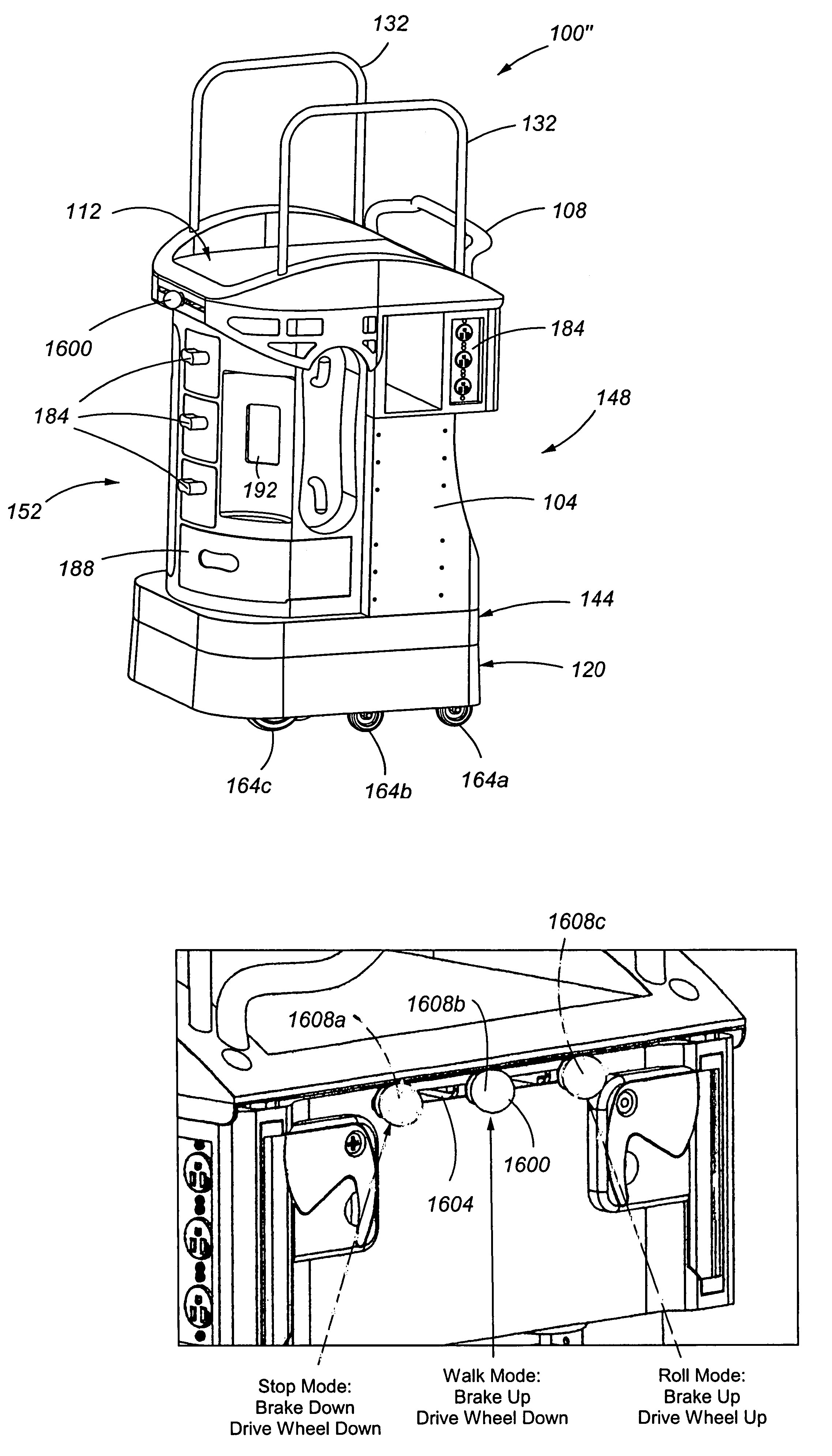
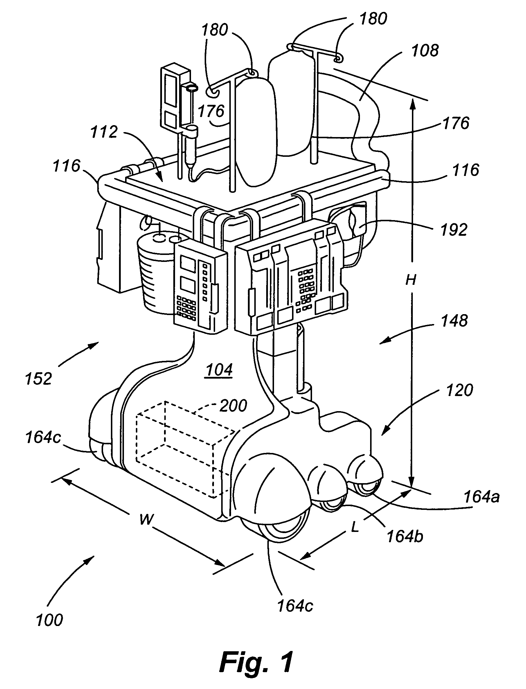
[0076]Referring now to FIG. 1, an apparatus constructed in accordance with an embodiment of the present invention is generally identified by reference numeral 100. Support platform 100 includes a chassis, support frame or body 104 having a platform handle 108 located at or near a top 112 of the platform 100. The platform 100 also includes a perimeter rail 116 at its top 112, wherein the perimeter rail 116 is adapted for receiving a variety of health monitoring, treatment, or maint...


PUM


Abstract

A patient support platform provides a solution for healthcare facilities and nursing staff to address patient and staff safety, patient mobility, patient comfort, the availability of patient information, monitoring drugs and therapy provided, and controlling health care expenses. The patient support platform preferably includes a transmission system that allows the patient and / or medical staff member to choose a stop, walk or roll mode. The transmission system preferably includes a drag wheel for applying a braking force in response to a voltage generated by a braking motor. The platform supports a plurality of devices that may be attached or associated with a patient throughout their stay at a healthcare facility. The support platform also preferably includes a mechanism for releasably attaching the support platform to another structure, such as a bed. Embodiments of the present invention include multiple non-medical uses of the platform.

Description

CROSS REFERENCE TO RELATED APPLICATION[0001]The present application claims the benefit, under 35 U.S.C.§119(e), of U.S. Provisional Patent Application Ser. No. 60 / 642,836 filed Jan. 10, 2005, entitled “MODULAR PATIENT SUPPORT SYSTEM”, the entire content of which is incorporated herein by reference in its entirety.FIELD OF THE INVENTION[0002]The present invention is directed to an apparatus used in the field of medicine, and more particularly, to a moveable and modular patient support system with a relatively small form factor.BACKGROUND OF THE INVENTION[0003]Current practice for patients in a healthcare facility involves having multiple unrelated treatment, maintenance and / or monitoring devices that are attached to the patient. These include intravenous fluids and drugs, drainage catheters, suction catheters, leg compression stockings and vital sign monitoring devices. Such devices often create a hazard for the patient both directly and indirectly. The myriad of devices may become e...

Claims


Application Information

Patent Timeline
Patent Type & Authority Patents(United States)
IPC IPC(8): A61H3/04
CPCA61B19/0248A61H3/04A61G12/001A61B2019/025A61H2003/046A61H2003/043A61B50/10A61B50/13
Inventor LIVENGOOD, JOSEPH C.LIVENGOOD, AMY L.PHILLIPS, BARRY T.ZIEMKOWSKI, THEODORE B.
Owner LIVENGOOD ENG
Why Eureka
Try Eureka