Method for thermally printing a dye image onto a three dimensional object using flexible heating elements

a technology of heating elements and dye images, which is applied in the directions of transfer printing, lithography, transportation and packaging, etc., can solve the problems of poor quality of printed images produced on objects, unfavorable use of inability to uniformly emit heat radiation by heating lamps, etc., to achieve the effect of improving flexibility

Inactive Publication Date: 2009-07-21
KII TEKU INC
View PDF19 Cites 60 Cited by
  • Summary
  • Abstract
  • Description
  • Claims
  • Application Information

AI Technical Summary

Benefits of technology

[0010]The image carrier sheet and / or flexible membrane can be preheated either before or after the step of establishing the vacuum. This preheating step improves the flexibility of the carrier sheet and / or membrane.
[0013]In another embodiment of this invention, a flexible membrane is not used in the thermal transfer printing process. This method includes the steps of: a) providing a three dimensional object having an outer plastic surface for receiving an image, wherein the object has a top surface and a plurality of side surfaces which are adjacent to and not co-planar with the top surface; b) placing a dye image carrier sheet in registration over the object, wherein the image carrier sheet has a pre-selected dye image printed thereon and the image carrier sheet carries a flexible heating element; c) establishing a vacuum under the image carrier sheet to cause the carrier sheet and flexible heating element to conform into pressurized communication with the top surface and side surfaces of the object; and d) heating the image carrier sheet with the flexible heating element to cause the image to transfer from the carrier sheet onto the top surface and side surfaces of the object. The image carrier sheet can be preheated to improve its flexibility before or after the step of establishing the vacuum.

Problems solved by technology

One drawback with the heating assembly described in the Durand, '084 Patent is that the mounted heat lamps are shown being located at some distance from the image sheet and object that will be printed thereon.
The heating lamps may not emit heat radiation uniformly to each area of the sheet and object.
As a result, the printed image, which is produced on the object, may be of poor quality.

Method used


Image

  • Method for thermally printing a dye image onto a three dimensional object using flexible heating elements
  • Method for thermally printing a dye image onto a three dimensional object using flexible heating elements
  • Method for thermally printing a dye image onto a three dimensional object using flexible heating elements

Examples


Embodiment Construction

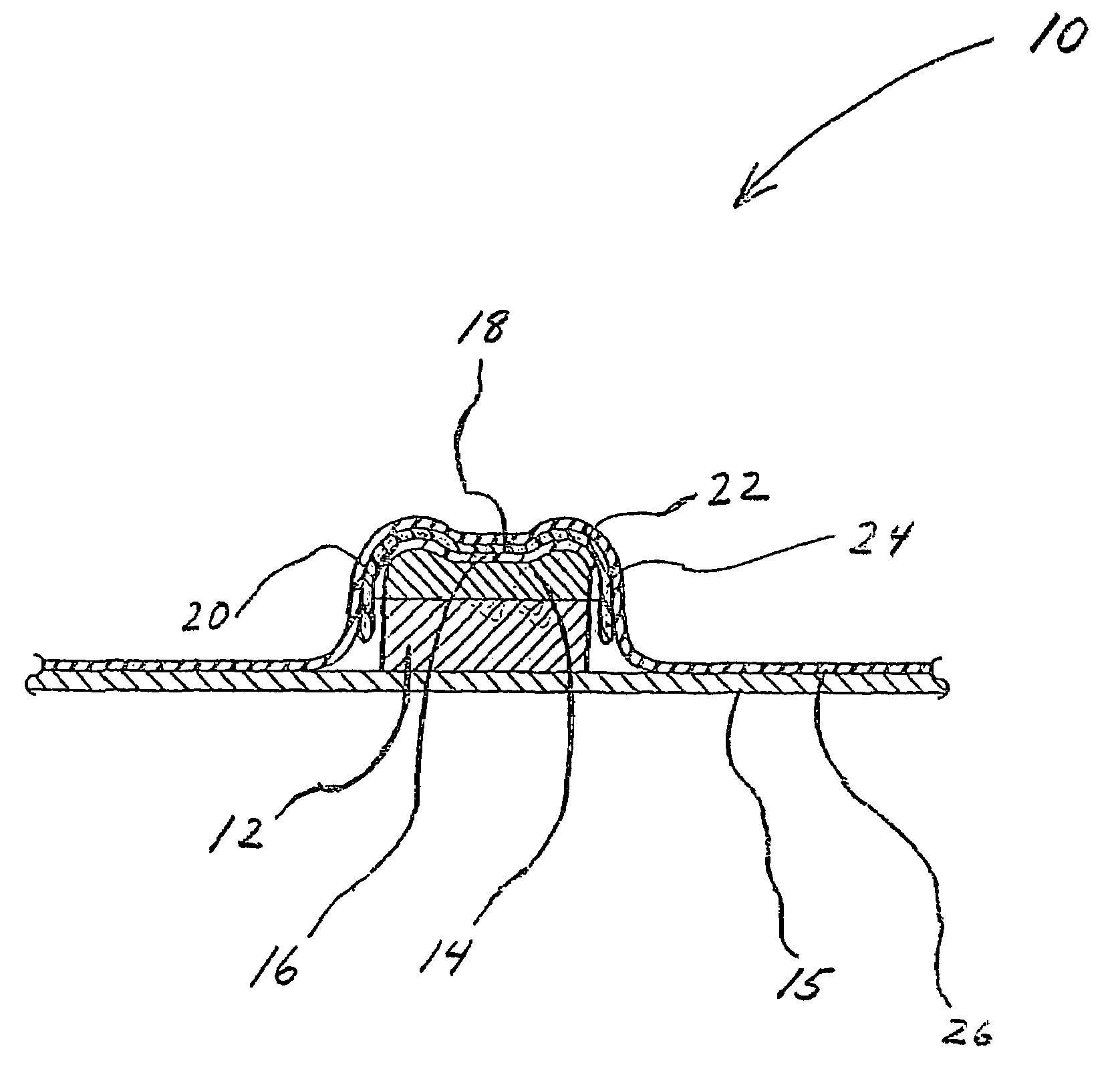
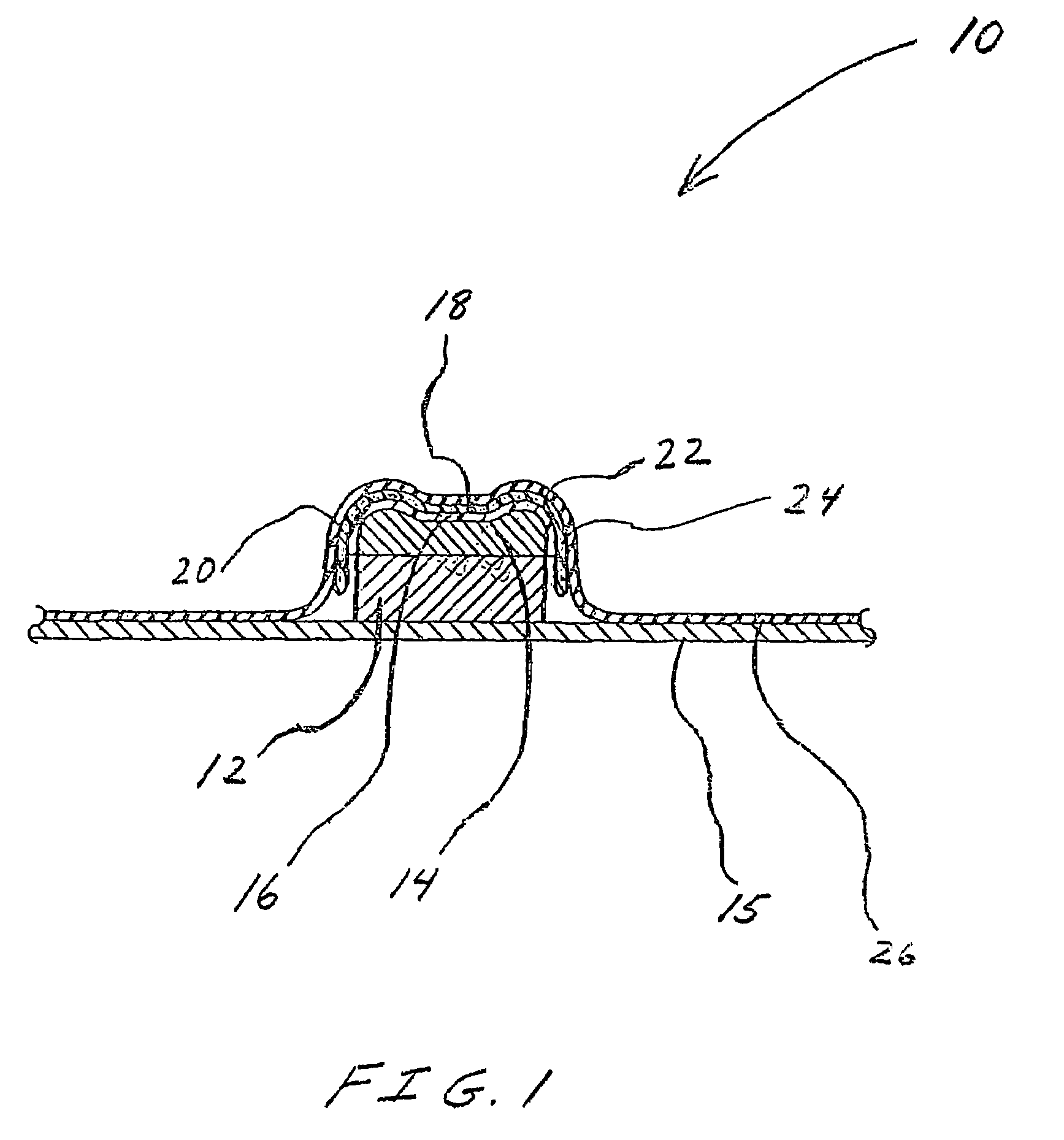
[0021]The thermal-transfer printing system, which is described in the aforementioned '062 Publication can be used in accordance with the present invention. Referring to FIG. 1, this printing assembly is generally indicated at 10. The assembly 10 includes a support fixture 12 having a molded base 14 thereon that is designed to support the specific object that will receive the pre-selected dye image. The support fixture 12 and molded base 14 are supported by support plate 15. The molded base 14 can be made from a silicone rubber material. In the embodiment shown in FIG. 1, the object is a plastic cellular telephone case 16. However, it is recognized that the assembly 10 can be used to apply the dye image to any other three dimensional object such as, for example, a computer mouse. As shown in FIG. 1, the assembly 10 can be used to transfer the dye image to a cellular telephone case 16 having a top surface 18 and side surfaces 20 and 22. A vacuum-formable carrier sheet 24 carrying the ...


PUM

PropertyMeasurementUnit
thicknessaaaaaaaaaa
thicknessaaaaaaaaaa
thicknessaaaaaaaaaa

Abstract

The present invention relates to a method for thermally printing a pre-selected dye image (45) onto a three dimensional object (16). The method involves placing an image carrier sheet (24) containing a pre-selected dye image (45) over the object (16). A flexible membrane (26) is lowered over the object (16) and the image carrier sheet (24). A vacuum is established under the membrane (26) causing the image carrier sheet (24) to conform to the shape of the object (16). The membrane (26) or image carrier sheet (24) carry flexible heating elements (36), which are heated, to thermally transfer the dye image (45) onto the object (16). The flexible heating elements (36) can be made by etching an electrical circuit in a metal foil (34) which is bonded to a film substrate (30).

Description

CROSS-REFERENCE TO RELATED APPLICATIONS[0001]This application claims the benefit of U.S. Provisional Application No. 60 / 482,732 having a filing date of Jun. 26, 2003, the entire contents of which are hereby incorporated by reference.BACKGROUND OF THE INVENTION[0002]The present invention relates to a method for thermally printing a pre-selected dye image onto a three dimensional object using flexible heating elements. Particularly, the heating elements are carried by a dye image carrier sheet or membrane which conforms tightly to the shape of the object during the printing operation.[0003]The dye image carrier sheet and membrane, which carry flexible heating elements in accordance with this invention, can be used with the thermal-transfer printing system described in published United States Patent Application US 2002 / 0131062 to Neri and Mutter (“'062 Publication”), the disclosure of which is hereby incorporated by reference.[0004]In general, the printing system described in the '062 ...

Claims


Application Information

Patent Timeline
Patent Type & Authority Patents(United States)
IPC IPC(8): B32B37/10B32B37/06B44C1/16B32B37/14B65C9/24H05B3/34B32B37/16B44C1/17C09J5/06B32B33/00B41M3/12B41M5/035G06T
CPCB41F16/00B44C1/1712B41M5/0358B41J2/3359B41M5/0256B32B37/10
Inventor FERGUSON, PATRICKNEWTON, PAUL GEOFFREYNERI, KENNETH
Owner KII TEKU INC
Why Eureka
Try Eureka