Short infrared zoom lens system

a technology of infrared zoom and lens assembly, applied in the field of optical systems, can solve the problems of inability of uncooled infrared detectors to make use of small band gap semiconductors, less sensitive, and uncooled detectors rely on other physical phenomena, so as to eliminate or reduce disadvantages and problems

Inactive Publication Date: 2009-07-21
REICHERT ABRAHAM
View PDF4 Cites 5 Cited by
  • Summary
  • Abstract
  • Description
  • Claims
  • Application Information

AI Technical Summary

Benefits of technology

[0008]In accordance with the present invention, a short length infrared zoom lens assembly having a constant F / Number is provided that substantially eliminates or reduces the disadvantages and problems associated with prior infrared detection systems.
[0011]Important technical advantages of the present invention include, without limitation, providing a relatively low cost short length infrared zoom lens assembly having a constant F / Number, and thus a constant sensitivity, over the zoom range. In particular, the location of the aperture stop allows the lens assembly to have a constant, very fast F / Number. Thus, the present invention eliminates the cost associated with large lenses for short length applications.

Problems solved by technology

Uncooled infrared detectors cannot make use of small band gap semiconductors because dark current swamps any signal at room temperature.
Consequently, uncooled detectors rely on other physical phenomena and are less sensitive than cooled detectors.
Short infrared zoom lenses having a fixed aperture stop, however, are typically expensive to manufacture due to the number and size of lens elements and to the materials needed to construct the lens elements.

Method used


Image

  • Short infrared zoom lens system
  • Short infrared zoom lens system
  • Short infrared zoom lens system

Examples


Embodiment Construction

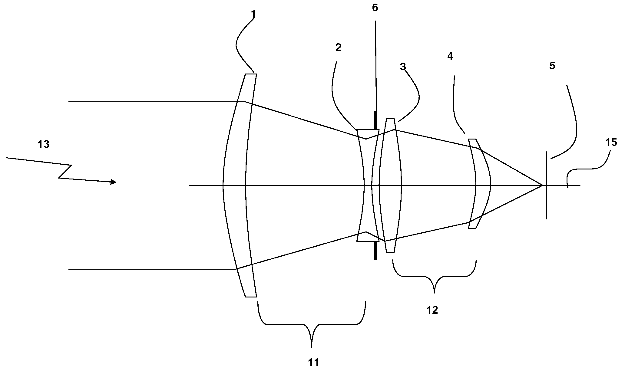
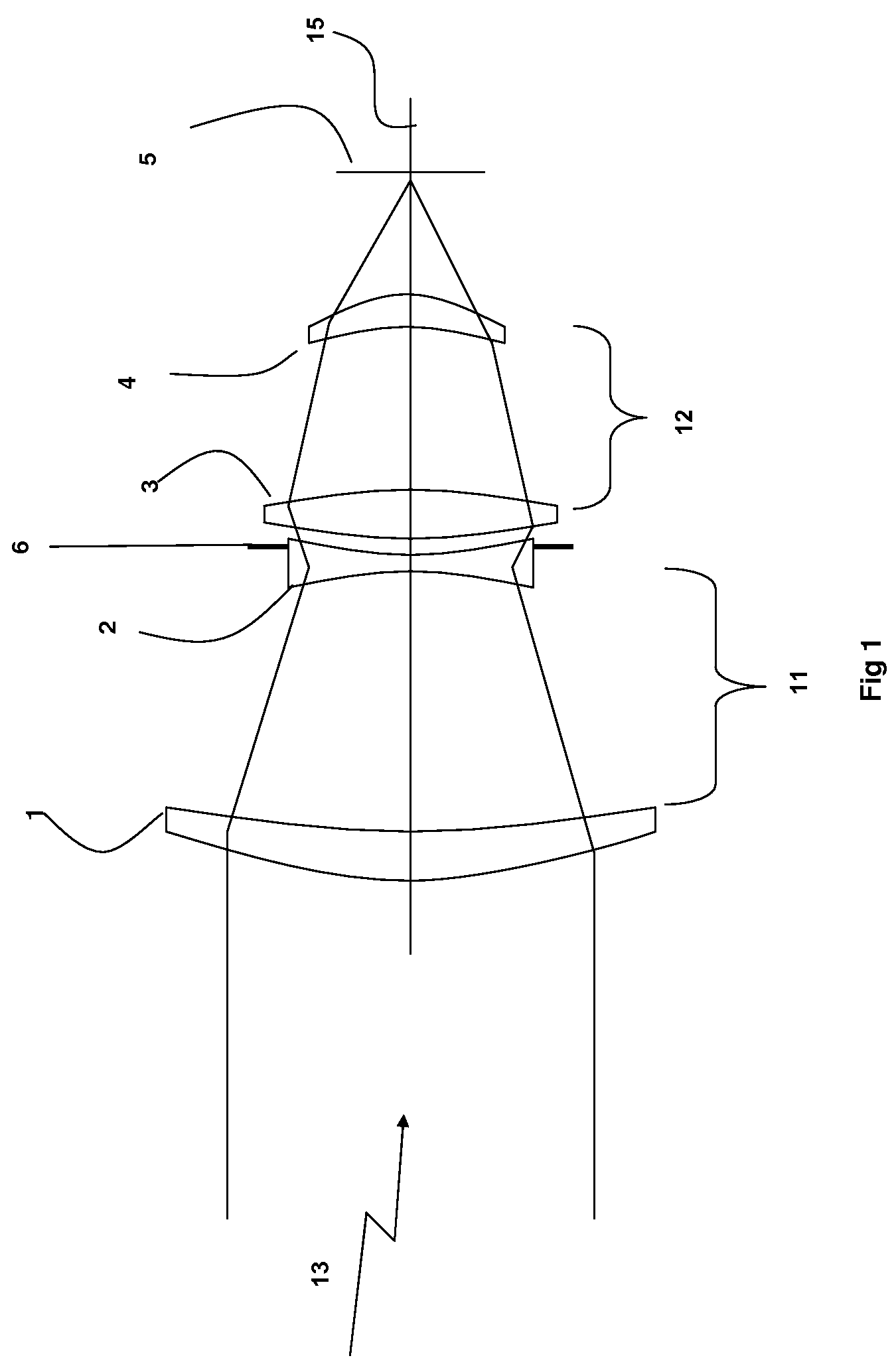
[0019]Reference is now made to FIG. 1, which illustrates a short length infrared zoom lens assembly, constructed and operative in accordance with an embodiment of the present invention. The short length zoom lens assembly focuses or directs infrared radiation emitted by an object 13 onto an image plane 5.

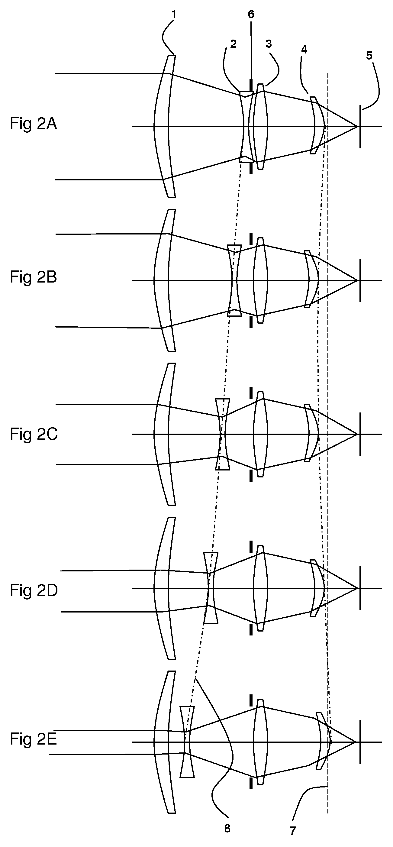
[0020]In this embodiment, the short length zoom lens assembly may be generally described as a zoom lens having a retracted position shown in FIG. 2A and an extended position shown in FIG. 2E. Preferably, the zoom lens assembly is approximately 90 millimeters in overall length and operable over a horizontal field of view of ten to forty degrees (10°-40°) and yielding a 4:1 zoom ratio with a 4:3 aspect ratio. Graphs of the performance of the short length zoom lens assembly verses spatial frequency are shown for the retracted zoom position in FIG. 3A and for the extended zoom position in FIG. 3B.

[0021]As shown by FIGS. 2A-2E, the various components of the short length zoom lens assembl...


PUM


Abstract

An infrared lens system including a focus section that focus infrared radiation at an image plane, and a zoom section that adjusts a desired focal length of the infrared radiation, the focus section and zoom section including a plurality of lens elements which are located along an optical axis in optical communication with each other, the focus section and zoom section each including a fixed lens fixed with respect to the optical axis and a movable lens arranged for movement along the optical axis.

Description

FIELD OF THE INVENTION[0001]The present invention relates generally to optical systems, and more particularly to a short infrared zoom lens assembly having a constant F / Number.BACKGROUND OF THE INVENTION[0002]Thermal imaging systems typically detect thermal radiance differences between various objects in a scene and display these differences in thermal radiance as a visual image of the scene. Thermal imaging systems are often used to detect fires, overheating machinery, planes, vehicles and people, and to control temperature sensitive industrial processes.[0003]The basic components of a thermal imaging system generally include optics for collecting and focusing infrared radiation from a scene, an infrared detector having a plurality of thermal sensors for converting infrared radiation to an electrical signal, and electronics for amplifying and processing the electrical signal into a visual display or for storage in an appropriate medium.[0004]Thermal imaging systems may use a variet...

Claims


Application Information

Patent Timeline
Patent Type & Authority Patents(United States)
IPC IPC(8): G02B13/14G02B15/14
CPCG02B15/173G02B13/14
Inventor REICHERT, ABRAHAM
Owner REICHERT ABRAHAM
Why Eureka
Try Eureka