Microscope

a microscope and beam technology, applied in the field of microscopes, can solve the problems of large adjustment complexity, high cost, and inability to combine beams with conventional optics, and achieve the effect of compact and structurally reliabl

Inactive Publication Date: 2009-07-21
LEICA MICROSYSTEMS CMS GMBH
View PDF17 Cites 10 Cited by
  • Summary
  • Abstract
  • Description
  • Claims
  • Application Information

AI Technical Summary

Benefits of technology

[0008]It is therefore the object of the present invention to disclose a microscope the light source of which may

Problems solved by technology

Combining beams with conventional optics is therefore both space consuming and very costly.
Furthe

Method used


Image

  • Microscope
  • Microscope

Examples


Embodiment Construction

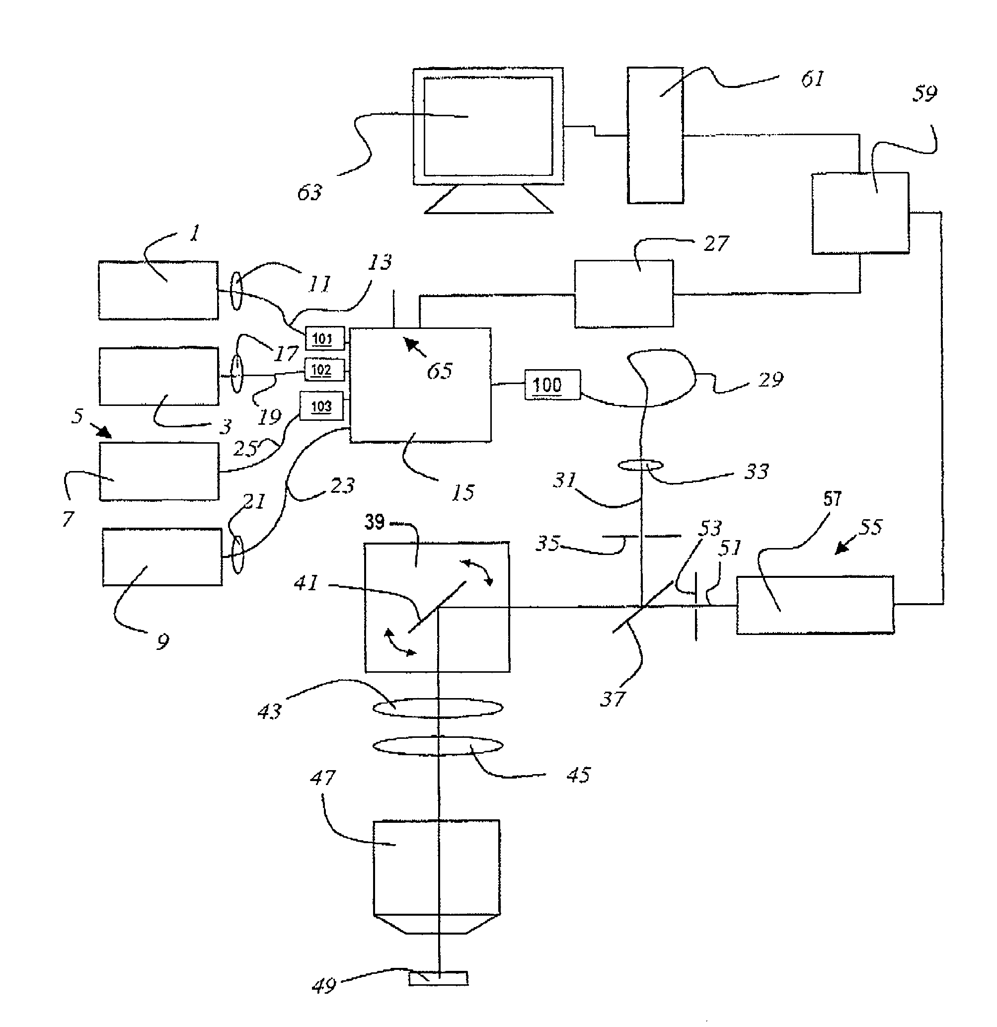
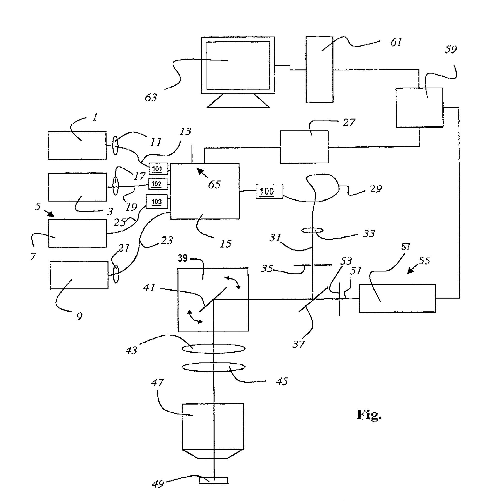
[0023]The figure shows a microscope according to the invention that is implemented as a confocal scanning microscope. The microscope exhibits a first light source 1 that is implemented as a laser light source, which emits light having a wavelength of 488 nm. Furthermore, the scanning microscope has a second light source 3 that is also implemented as a laser, and which emits light having a wavelength of 532 nm. The scanning microscope comprises a third light source 5 that is implemented as a pigtail laser 7, which emits light having a wavelength of 635 nm. Furthermore, the scanning microscope has a fourth light source 9 that is also implemented as a laser, and which emits a light source having a wavelength of 405 nm.

[0024]The light from the first light source 1 is coupled with a first coupling optic 11 to a first light-guiding fiber 13, which is coupled to a fiber multiplexer 15. The light from the second light source 3 is coupled with a second coupling optic 17 to a second light-gui...


PUM


Abstract

The invention relates to a microscope comprising at least one first and second light sources, a first light-guiding fiber connected to the first light source and a second light-guiding fiber connected to the second light source, wherein the light emitted by corresponding light source is injectable into the connected light-guiding fiber. The inventive microscope also comprises an objective lens disposed in the illumination beam path and is characterized in that a fiber multiplexer connected to the first and second light-guiding fibers, receiving the light from the light source and selectively allowing the light from the first or second light source to pass is disposed in the illumination beam path.

Description

FIELD OF THE INVENTION[0001]The invention relates to a microscope with at least a first light source and a second light source, whereby the first light source is coupled to a first light-guiding fiber and the second light source is coupled to a second light-guiding fiber, and whereby the light emitted by each light source is coupled to the connected light-guiding fiber and to an objective arranged in an illumination beam path.BACKGROUND OF THE INVENTION[0002]In scanning microscopy, a sample is scanned with a light beam in order to observe the reflection or fluorescent light emitted by the sample. Lasers are frequently used as the light source for this purpose. For example, an arrangement with a single laser that emits several laser lines is known from EP 0 495 930, “Confocal microscope system for multicolor fluorescence.” Currently, mixed gas lasers, in particular ArKr lasers are usually used for the purpose. The focus of an illumination light beam is moved in an object plane with t...

Claims


Application Information

Patent Timeline
IPC IPC(8): G02B21/06G02B21/00
CPCG02B21/0032G02B21/06G02B21/0052
Inventor LEIMBACH, VOLKERULRICH, HEINRICH
Owner LEICA MICROSYSTEMS CMS GMBH
Why Eureka
Try Eureka