Method for inspecting ceramic structures

a ceramic structure and inspection method technology, applied in material analysis using wave/particle radiation, instruments, nuclear engineering, etc., can solve the problems of affecting the filtration performance or the ability, the method is not suitable for inspecting the pore size of the filter, and the method is not suitable for inspecting the shape and size of the defect, etc., to achieve the effect of short tim

Active Publication Date: 2009-07-21
NGK INSULATORS LTD
View PDF11 Cites 8 Cited by
  • Summary
  • Abstract
  • Description
  • Claims
  • Application Information

AI Technical Summary

Benefits of technology

[0010]Accordingly, an object of the present invention is to provide a nondestructive method for inspecting ceramic structures, the method which not only easily detects the position and size of an internal defect in a ceramic structure in a short time, but also accurately identifies the position, shape, and size of the internal defect.
[0019]The method of the present invention can easily and three-dimensionally identify the position, shape, and size of the internal defect in a ceramic structure in a nondestructive manner in a short time.

Problems solved by technology

If the ceramic structure has large holes penetrating the porous partition wall, the large holes negatively affect the filtration performance or the ability to function as a catalyst carrier of the ceramic structure, and bring about defects.
Unfortunately, the method allows the powder to remain in the filter, and the remaining powder must be removed.
Also, this method is not suitable for inspecting the pore size of the filter because the powder cannot be discharged unless the filter has pinholes.
This method is advantageous in identifying the position of the defect in the cross-sectional direction, but unsuitable for inspecting the shape and size of the defect.
Destructive inspection is much expensive in time and effort and less accurate.
Specimens subjected to destructive inspection are not used for other inspections for evaluating the entirety of the product, such as strength, disadvantageously.
However, this method has been mainly approached from the viewpoint of increasing the voltage of the X-ray tube to enhance the spatial resolution (that is, how finely the apparatus can inspect a test body), but has not taken into account the density resolution (that is, for example, how finely the apparatus can show the difference in density among adjacent materials in a test body).
Consequently, this method cannot sufficiently estimate the density of particularly ceramic structures, and thus makes unclear the boundary between the internal defect and the internal structure.
Thus, it has been difficult to accurately identify the position, shape, and size of the internal defect.

Method used


Image

  • Method for inspecting ceramic structures
  • Method for inspecting ceramic structures
  • Method for inspecting ceramic structures

Examples


examples

[0037]The present invention will now be further described in detail with reference to examples. However, the invention is not limited to the scope of the examples.

examples 1 and 2

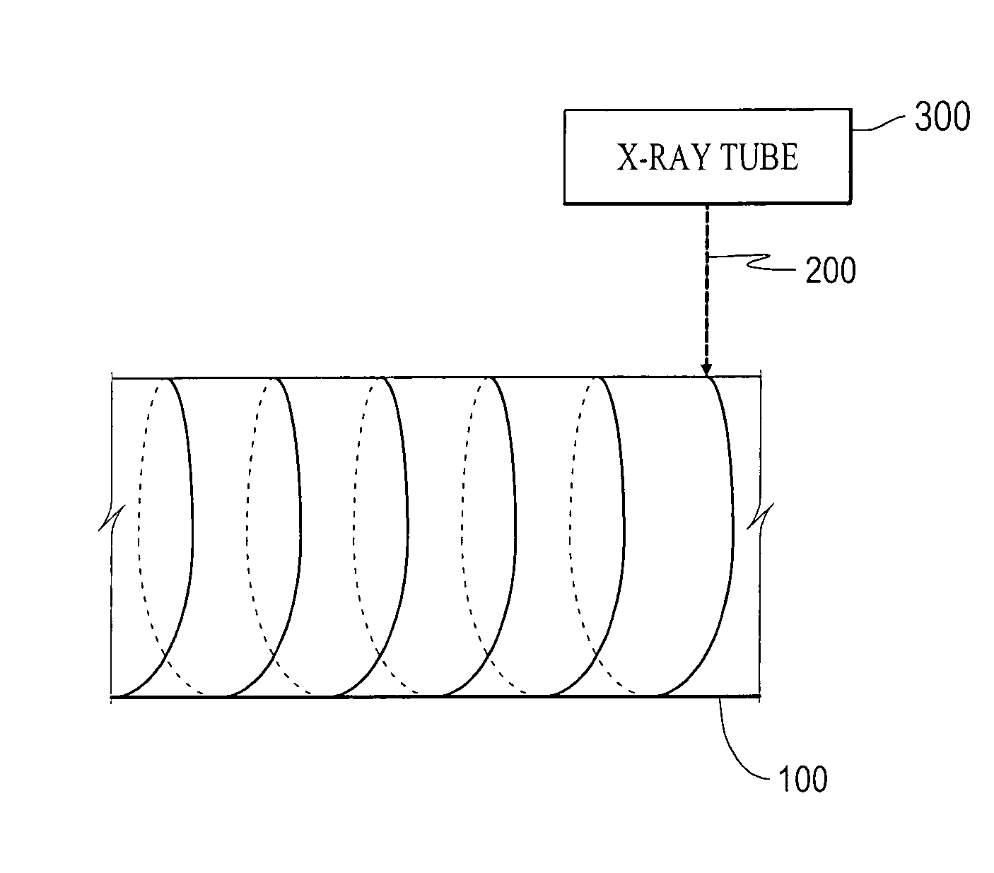
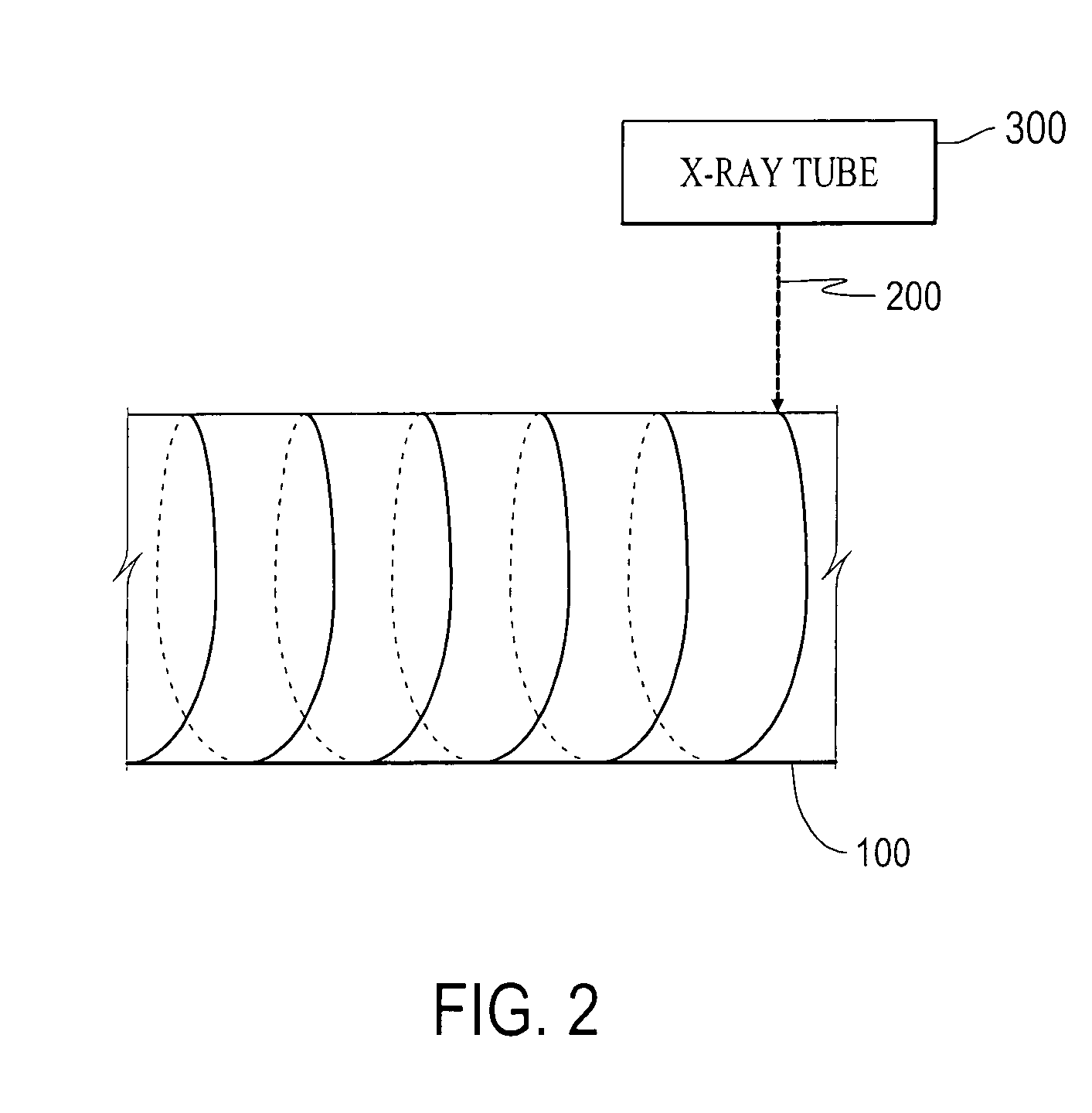
(1) Preparation of Honeycomb Structure

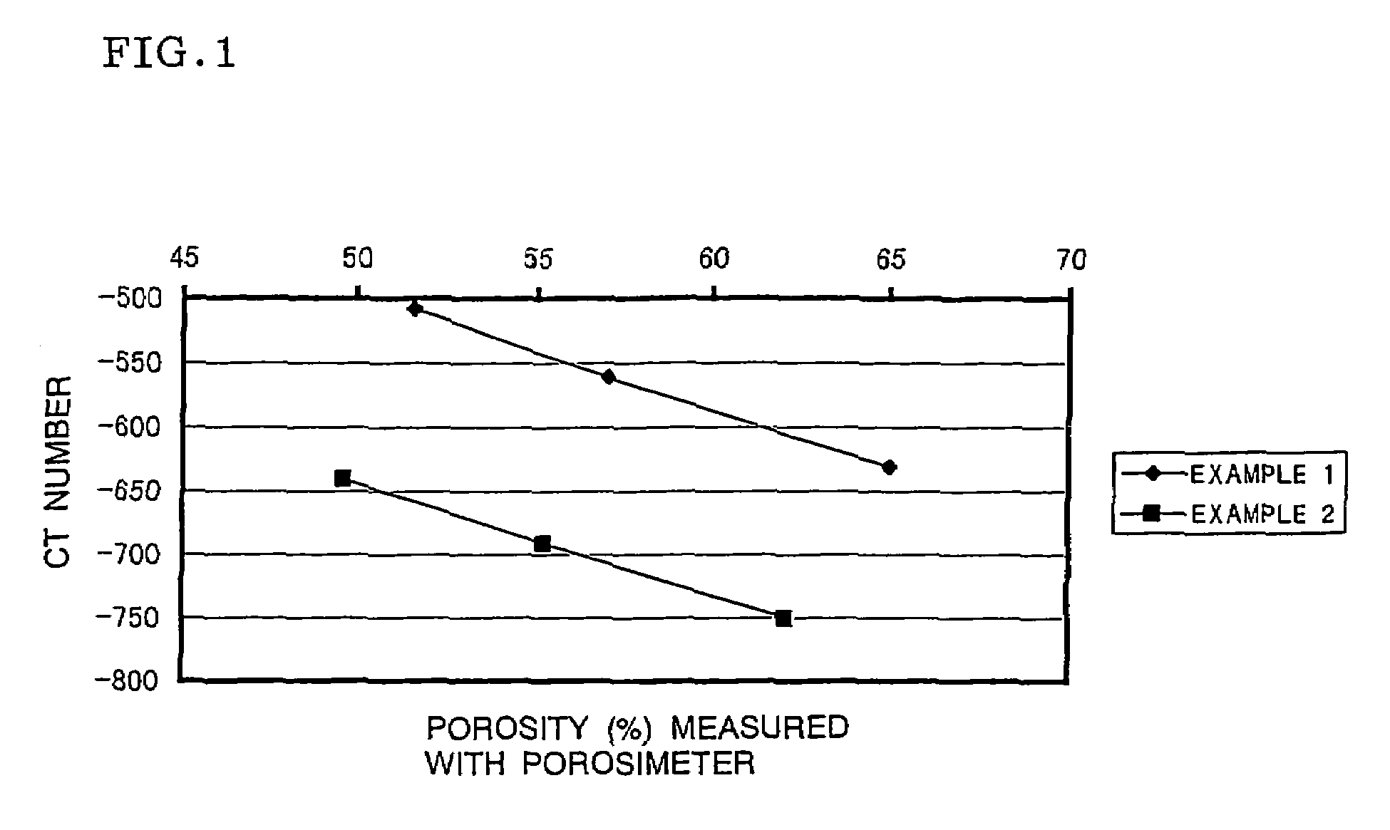
[0038]Powder compositions of cordierite were compounded so that the porosities would be 50%, 60%, and 65% after firing. A binder and water were added to the compositions, and the mixtures were kneaded and plugged to prepare three pieces of clay. Then, each of the three pieces of clay was formed and dried to yield a dried honeycomb body. In this process, Example 1 used an extrusion die having rectangular cells with a cell density of 300 cells / in2, a rib thickness of 12 mills, and an open frontal area of 62.8%, and Example 2 used an extrusion die having rectangular cells with a cell density of 100 cells / in2, a rib thickness of 17 mills, and an open frontal area of 68.9%. Both ends of the dried body were cut off to form flat and smooth surfaces. The resulting body was coated with a film and provided with holes in a checkered pattern with a laser. Then, a slurry of a cordierite composition was prepared and press-fitted into the honeycomb carrier to ...


PUM

PropertyMeasurementUnit
tube currentaaaaaaaaaa
tube voltageaaaaaaaaaa
tube currentaaaaaaaaaa

Abstract

There is provided a nondestructive method for inspecting ceramic structures, the method which not only easily detects the position and size of an internal defect in a ceramic structure in a short time, but also accurately identifies the position, shape, and size of the internal defect. In the method, the distribution of X-ray absorption coefficients (CT numbers) at fault planes of the ceramic structure is measured by irradiating the periphery of the ceramic structure with X rays along the periphery of the ceramic structure so that the X rays scan the entire periphery. The X rays are emitted from an X-ray tube at a tube voltage in the range of 80 to 400 kV and a tube current in the range of 2 to 400 mA.

Description

TECHNICAL FIELD[0001]The present invention relates to a method for inspecting ceramic structures in which the distribution of X-ray absorption coefficients (CT numbers) at the fault planes of a ceramic structure is measured by irradiating the ceramic structure with X rays along the periphery of the ceramic structure so that the x rays scan the entire periphery, and particularly to an inspection method using high density resolution X-ray computed tomography (CT).BACKGROUND ART[0002]Ceramic structures (for example, honeycomb structures) are often used for filters and catalyst carriers, for example, in exhaust gas purifying systems of heat engines, such as internal combustion engines, and combustion equipment, such as boilers, in liquid or gaseous fuel reformers, and in water and sewage purifying systems. In particular, ceramic structures are suitably used in diesel particulate filters (hereinafter referred to as DPFs) or high-temperature gas dust collector for collecting and removing ...

Claims


Application Information

Patent Timeline
Patent Type & Authority Patents(United States)
IPC IPC(8): G01N23/02G01N23/00G01N15/08G01N23/04
CPCG01N23/046G01N2223/419
Inventor KATO, SHIGEKI
Owner NGK INSULATORS LTD
Why Eureka
Try Eureka