Transient liquid phase bonding using sandwich interlayers

a technology of liquid phase bonding and sandwich interlayer, which is applied in the direction of turbines, manufacturing tools, solventing apparatus, etc., can solve the problems of affecting the bonding effect of the substrate, the current transient liquid phase bonding system and method does not produce enough strong bonds between the substrate for some applications, and the component distortion, etc., to achieve uniform hardness, strong bonding, and uniform hardness. uniform

Active Publication Date: 2009-07-28
RTX CORP
View PDF23 Cites 36 Cited by
  • Summary
  • Abstract
  • Description
  • Claims
  • Application Information

AI Technical Summary

Benefits of technology

[0006]Accordingly, the above-identified shortcomings of existing systems and methods are overcome by embodiments of the present invention, which relates to transient liquid phase bonding systems and methods. These systems and methods utilize sandwich interlayers to form stronger, more homogeneous bonds than currently possible with existing transient liquid phase systems and methods. These sandwich interlayers also allow finer microstructures and more uniform hardnesses to be obtained in such bonds.

Problems solved by technology

However, diffusion bonding requires high pressures, which can cause distortion of the components.
Current transient liquid phase bonding systems and methods do not produce sufficiently strong bonds between substrates for some applications.

Method used


Image

  • Transient liquid phase bonding using sandwich interlayers
  • Transient liquid phase bonding using sandwich interlayers
  • Transient liquid phase bonding using sandwich interlayers

Examples


example 1

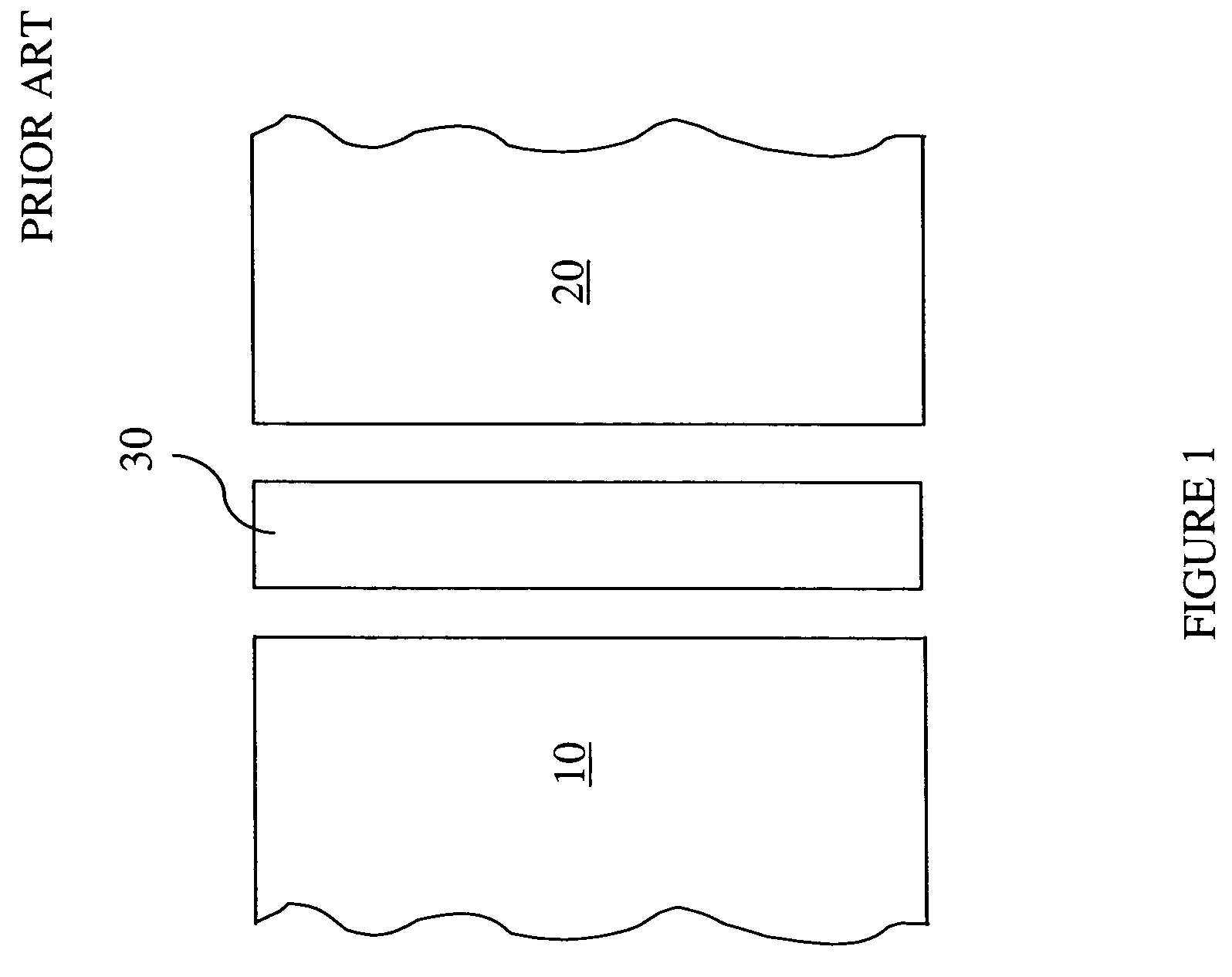
[0038]In this first sample, a single sheet of MBE 80 nickel-based brazing foil was utilized as the single interlayer 30 to join the single crystal substrate 10 to the polycrystal line substrate 20, as shown in FIG. 1. The amorphous sheet of MBF 80 nickel-based brazing foil was about 25 microns thick, and had a nominal composition of: 79.3 wt. % nickel, 15.3 wt. % chromium, 1.5 wt. % iron, 0.1 wt. % cobalt, 0.1 wt. % titanium, 0.1 wt. % aluminum, 3.7 wt. % boron 0.1 wt. % carbon. This commercially available MBF 80 nickel-based brazing foil was selected to provide approximately uniform chemical distribution across the bond region after solidification thereof. The boron in this sheet is a melting point depressant which allows the MBF 80 nickel-based brazing foil, to melt at about 1940° F., which is below the gamma prime solvus temperatures for both the single crystal substrate 10 and the polycrystalline substrate 20 utilized here.

[0039]TLP bonding was accomplished in this sample at a t...

example 2

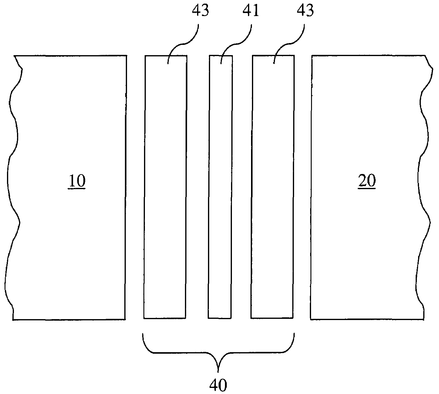
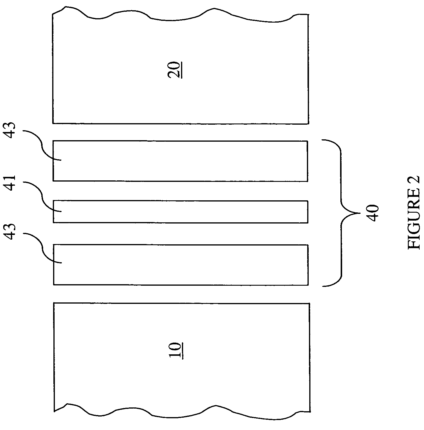
[0042]In this second sample, an exemplary sandwich interlayer 40 of this invention was utilized to join the single crystal substrate 10 to the polycrystalline substrate 20, as shown in FIG. 2. The sandwich interlayer 40 comprised two outer layers 43 and a middle layer 41 sandwiched between the two outer layers 43. Each outer layer 43 comprised an amorphous sheet about 25 microns thick of the same MBF 80 nickel-based brazing foil used in Example 1. The middle layer 41 comprised a layer of 10 micron powder about 100 microns thick having the following nominal composition: 60 wt. % Ni, 12.4 wt. % Cr, 18.5 wt. % Co, 3.2 wt. % Mo, 5.0 wt. % Al, 4.3 wt. % Ti, 0.8 wt. % V, 0.1 wt. % Zr, 0.1 wt. % C, and 0.02 wt. % B. The total thickness of this sandwich interlayer 40 was about 150 microns thick, and the final bonded area was about 250 microns thick due to coarsening during bonding.

[0043]The same bonding parameters as utilized in Example 1 were utilized here. As before, TLP bonding was accom...


PUM

PropertyMeasurementUnit
thickaaaaaaaaaa
thickaaaaaaaaaa
timeaaaaaaaaaa

Abstract

Systems and methods for transient liquid phase bonding are described herein. Embodiments of these systems and methods utilize sandwich interlayers to produce stronger, more homogeneous bonds than currently possible. These sandwich interlayers have a middle bonding layer sandwiched between two outer bonding layers. The middle bonding layer is a different composition, and may even be a different form, than the outer bonding layers. In embodiments, these sandwich interlayers may be used to join a single crystal material to a polycrystalline material to make a gas turbine engine component, such as an integrally bladed rotor.

Description

STATEMENT REGARDING FEDERALLY SPONSORED RESEARCH OR DEVELOPMENT[0001]The U.S. Government may have certain rights in this invention pursuant to Contract Number F33615-98-C-2823 with the United States Air Force.FIELD OF THE INVENTION[0002]The present invention relates generally to bonding techniques. More specifically, the present invention relates to sandwich interlayers for use in transient liquid phase bonding.BACKGROUND OF THE INVENTION[0003]Various items, such as gas turbine engine components, can be manufactured by joining individually fabricated segments together to form a single, unitary component. Cracks or other damage in such components may also be repaired. Diffusion bonding, which involves the solid-state movement of atoms and grain growth across a joint interface, has been used to join and / or repair such components. Diffusion bonding allows for the fabrication and repair of complex assemblies having bonded areas that are practically indistinguishable from the adjacent se...

Claims


Application Information

Patent Timeline
Patent Type & Authority Patents(United States)
IPC IPC(8): B23K35/12B23K35/24
CPCB23K20/02B23K2201/001B23K2101/001B29C44/30
Inventor DAS, GOPAL
Owner RTX CORP
Why Eureka
Try Eureka