Fuel storage tank pressure management system and method employing a carbon canister

a technology of pressure management system and carbon canister, which is applied in the direction of transportation and packaging, liquid transfer devices, separation processes, etc., can solve the problems of carbon canisters that require little or no maintenance and have a very long working life, and achieve the effect of improving hydrocarbon adsorption and more evenly spreading air flow

Active Publication Date: 2009-07-28
VEEDER ROOT
View PDF36 Cites 20 Cited by
  • Summary
  • Abstract
  • Description
  • Claims
  • Application Information

AI Technical Summary

Benefits of technology

[0014]The present invention provides a canister filled with hydrocarbon adsorbing activated carbon (carbon canister) to adsorb hydrocarbons from a hydrocarbon air mixture in the ullage of a UST system to prevent fugitive emissions due to overpressurization, with an inlet port at one end attached though a tube or other connection means to the tank vent line or other vapor access point of a UST system. An outlet port on the opposite end of the canister is connected to a flow-limiting orifice with a known calibrated flow rate that vents in a controlled fashion to the atmosphere. When UST pressure rises slightly above ambient, fuel vapors and air from the UST system enters, via the inlet port, into the canister, where hydrocarbons are adsorbed onto the activated carbon. The cleansed air vents through the controlled flow outlet port to atmosphere. The removal of fuel vapor and air from the UST system limits pressure in the UST system and prevents excessive positive pressure from occurring. The activated carbon is purged of hydrocarbons by means of reverse air flow caused by negative UST pressures that occur during periods of ORVR vehicle refueling.
[0015]This solution of the present invention is small, low cost and is easily installed without requiring electrical power or any controlling mechanisms. Bidirectional flow, including purging, is driven passively by the normal positive and negative pressures that occur in UST systems, typically in a diurnal cycling manner as opposed to systems requiring an active vacuum or pressure component, such as a vacuum pump, to direct the hydrocarbon air mixture from the UST to the canister. Thus, the carbon canister requires little or no maintenance and has a very long working life.
[0017]In an alternative carbon canister embodiment, the canister is only comprised of one internal chamber. The canister is coupled to the outside of the vent pipe coupled to the UST. A tube, hose, or other coupling means is coupled between the inlet port of the carbon canister and the vent pipe to couple the canister to the UST to receive the hydrocarbon air mixture. A diffuser may also be employed to diffuse the air entering into the canister to more evenly spread the air flow across the cross-section of the canister. Further, packing components internal to the canister may be employed to tightly pack the carbon together inside the canister to improve hydrocarbon adsorption.

Problems solved by technology

Thus, the carbon canister requires little or no maintenance and has a very long working life.

Method used


Image

  • Fuel storage tank pressure management system and method employing a carbon canister
  • Fuel storage tank pressure management system and method employing a carbon canister
  • Fuel storage tank pressure management system and method employing a carbon canister

Examples


Embodiment Construction

[0018]The embodiments set forth below represent the necessary information to enable those skilled in the art to practice the invention and illustrate the best mode of practicing the invention. Upon reading the following description in light of the accompanying drawing figures, those skilled in the art will understand the concepts of the invention and will recognize applications of these concepts not particularly addressed herein. It should be understood that these concepts and applications fall within the scope of the disclosure and the accompanying claims.

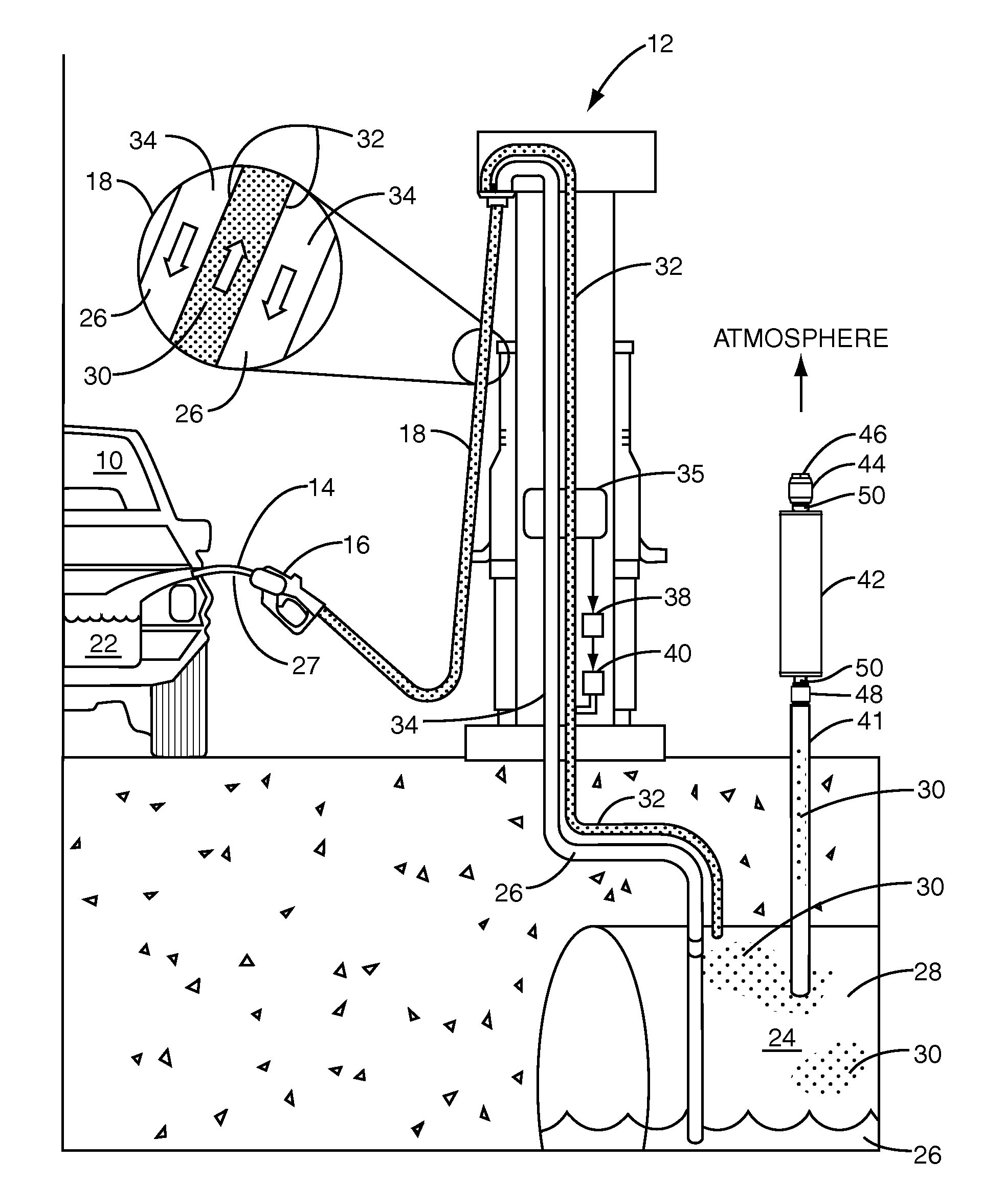
[0019]FIG. 1 illustrates a typical Stage II vapor recovery-equipped fuel dispensing system in a service station environment employing a carbon canister in accordance with the present invention for adsorbing hydrocarbons from the UST. A vehicle 10 is proximate to a fuel dispenser 12 for refueling. The fuel dispenser 12 contains a nozzle 16 that contains a spout 14. The nozzle 16 is connected to a hose 18, which is fluidly coupled t...


PUM

PropertyMeasurementUnit
diameteraaaaaaaaaa
diameteraaaaaaaaaa
pressureaaaaaaaaaa

Abstract

A carbon canister to adsorb hydrocarbons from a hydrocarbon air mixture in a UST system to prevent fugitive emissions due to overpressurization. The carbon canister has an inlet port at one end coupled to the UST system. An outlet port on the opposite end of the canister is connected to a flow-limiting orifice with a known calibrated flow rate that vents in a controlled fashion to the atmosphere. When UST pressure rises slightly above ambient pressure, fuel vapors and air from the UST system enters, via the inlet port, into the canister, where hydrocarbons are adsorbed onto the surface of the activated carbon. The cleansed air vents through the controlled flow outlet port to atmosphere, thereby preventing excessive positive pressure from occurring in the UST system. The activated carbon is purged of hydrocarbons by means of reverse air flow caused by negative UST pressures that occur during periods of ORVR vehicle refueling.

Description

RELATED APPLICATIONS[0001]This application claims priority to U.S. Provisional Patent Application No. 60 / 723,757 entitled “FUEL STORAGE TANK PRESSURE MANAGEMENT SYSTEM AND METHOD EMPLOYING A CARBON CANISTER,” filed on Oct. 5, 2005, and U.S. Provisional Patent Application No. 60 / 811,360 entitled “FUEL STORAGE TANK PRESSURE MANAGEMENT SYSTEM AND METHOD EMPLOYING A CARBON CANISTER,” filed on Jun. 6, 2006, both of which are incorporated herein by reference in their entireties.FIELD OF THE INVENTION[0002]The present invention relates to a fuel storage tank pressure management system and method employing a carbon canister to adsorb hydrocarbons and reduce pressure inside a fuel storage tank to prevent fugitive emissions. Adsorbed hydrocarbons are returned to the fuel storage tank during underpressurization conditions.BACKGROUND OF THE INVENTION[0003]The growing population of vehicles in the U.S. with Onboard Refueling Vapor Recovery (ORVR) equipment installed is resulting in increased vap...

Claims


Application Information

Patent Timeline
Patent Type & Authority Patents(United States)
IPC IPC(8): B01D53/04
CPCB01D53/0407B67D7/0478B01D53/0454B01D2253/102B01D2257/702B01D2259/40009B01D2259/40086B01D2259/4516B01D2257/7022
Inventor HART, ROBERT P.REID, KENT
Owner VEEDER ROOT
Why Eureka
Try Eureka