Vehicle vision system

a vision system and vehicle technology, applied in the field of vehicle vision systems, can solve the problems of inability to modify the color balance for night vision, blind spots, wind resistance, etc., and achieve the effect of preventing compromising the night vision of the driver and high display light levels

Inactive Publication Date: 2009-07-28
GENTEX CORP +1
View PDF125 Cites 332 Cited by
  • Summary
  • Abstract
  • Description
  • Claims
  • Application Information

AI Technical Summary

Benefits of technology

[0011]Another object of the present invention is to provide a system and method of displaying an image of a scene with minimal exposure of the driver to high display light levels and glare which may impair night vision.
[0012]Another object of the present invention is to provide a system and method of displaying an image of a scene with appropriate color balance to prevent compromising the night vision of a driver.
[0013]Another object of the present invention is to provide a system and method for viewing details in scenes that may be obscured due to dim lighting or masked by bright light sources.
[0014]Still another object of the present invention is to provide a system and method for viewing scenes with wide inter-scene brightness levels.

Problems solved by technology

The use of mirrors has resulted in several difficulties, including blind spots due to opaque body structures, distortion due to convexity, inability to modify color balance for night vision, and wind resistance due to outside mounting.
Another difficulty with current vehicle viewing systems is an inability to properly display the intensity of a dimly lit scene.
Viewing relatively bright images, such as a display screen with a relatively high intensity, causes changes in the retina which substantially and subtly reduce visual sensitivity to dimly lit scenes.
Following exposure to brighter lights, this effect reduces the perception of and resulting reaction time to dimly lit scenes.
Still another difficulty with current vehicle viewing systems is the inability to alter the balance between a dim and bright portion of a scene.
For example, headlamps of a trailing vehicle are frequently annoying to a driver.
Electrochromic mirrors have eliminated most of the annoyance glare without darkening excessively but cannot alter the balance between dim and bright portions of the same scene and cannot effectively amplify the intensity of a dimly lit scene.
Yet another difficulty with current vehicle viewing systems is the inability to shift the color balance of a displayed scene in response to changing ambient light conditions.
In particular, blue light is more damaging to night vision than red light.

Method used


Image

  • Vehicle vision system
  • Vehicle vision system
  • Vehicle vision system

Examples


Embodiment Construction

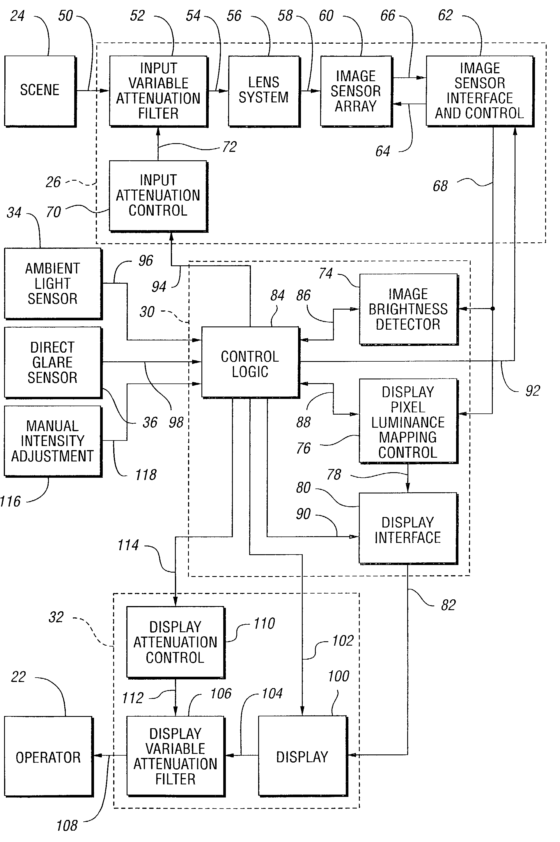
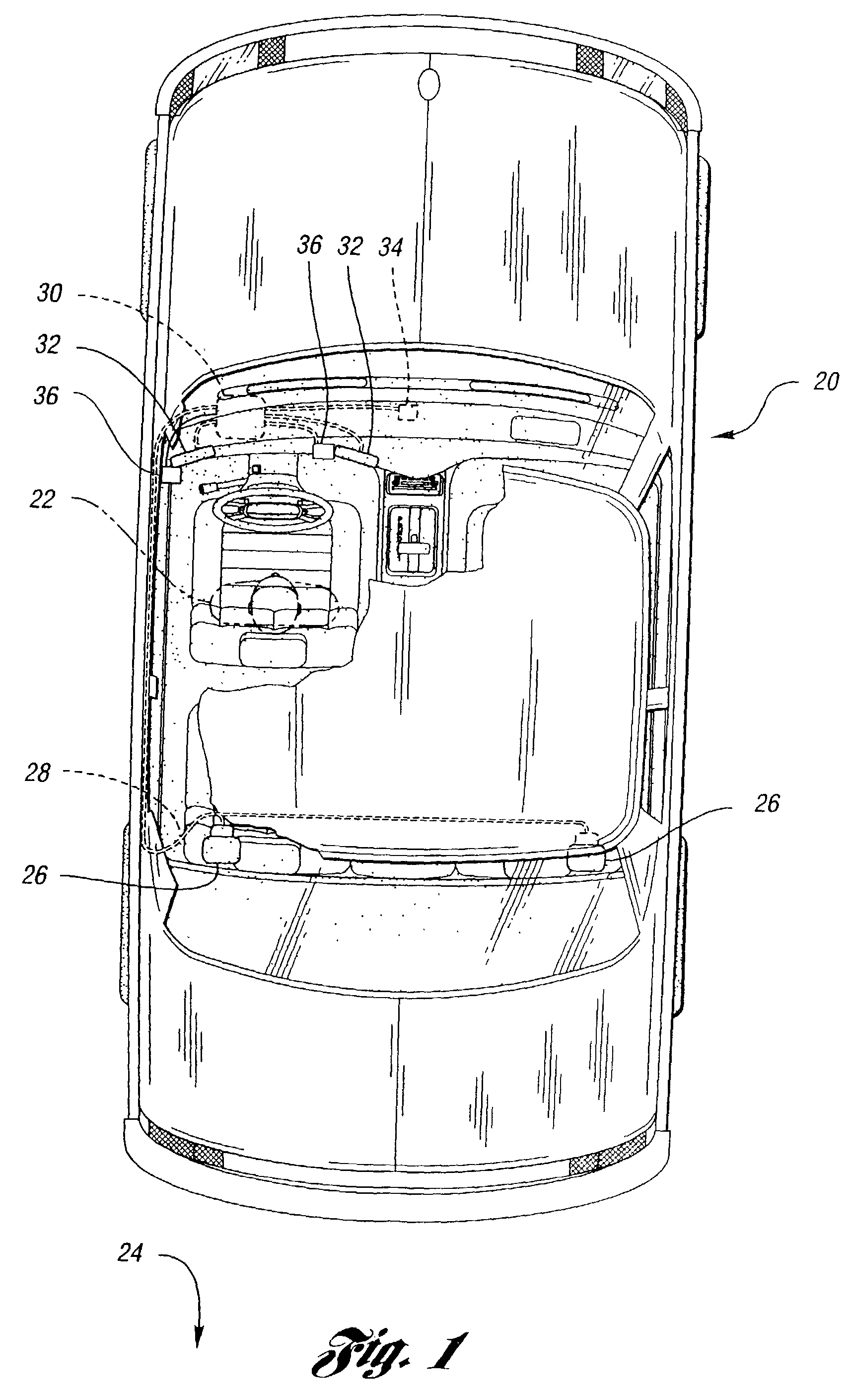
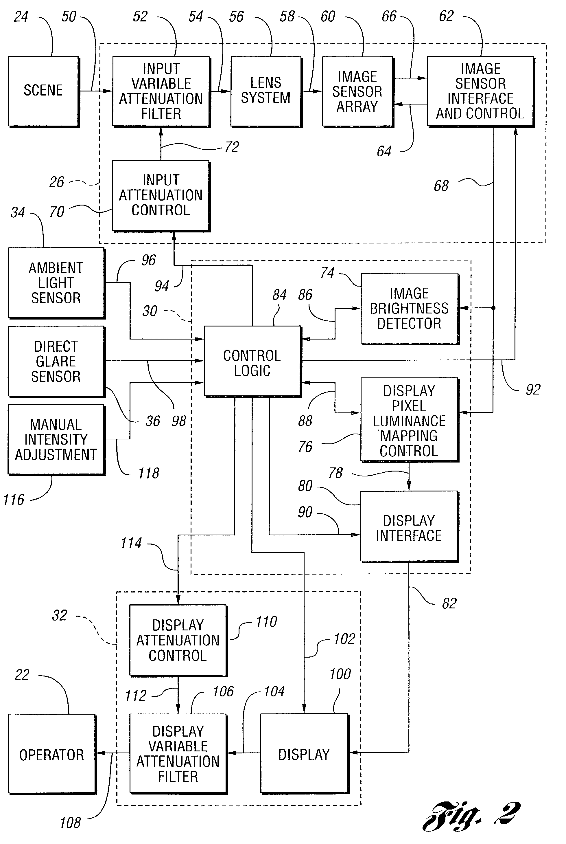
[0031]Referring now to FIG. 1, a schematic diagram of the present invention is shown. Vehicle 20 is driven by operator 22. One or more camera systems 26 are operative to view a scene 24. In the example shown, scene 24 is generally behind vehicle 20. Of course, however, camera system 26 may be oriented in a variety of ways to view scenes at other locations about vehicle 20 including, but not limited to, the sides, back, front, bottom, top, and inside. In the example shown, signals representative of the scene are sent via channel 28 to a processor system 30. Input from an ambient light sensor 34 and direct glare sensor 36 is also available to processor system 30. Processor system 30 produces an enhanced image of scene 24 on one or more display systems 32.

[0032]In a particularly useful embodiment, a conventional mirror system is augmented by camera systems 26 which cover a wide field of view to the back and sides so that pedestrians or other objects directly back of vehicle 20 may be s...


PUM


Abstract

A vehicle viewing system including a camera system for generating a signal corresponding to a scene by integrating light from the scene incident on pixel cells having a variable integration time, a display system for presenting a visual representation of the scene, and a processor system operable to determine the camera system integration time based on brightness levels in the scene. The camera system preferably includes and an input attenuating filter to limit light striking the optical array. The processor system includes an image brightness detector to determine overall image brightness and a display control to determine luminance settings for the display system. The processor system may determine the intensity of the display system based on the brightness of the scene, ambient light levels, and glare on the display. The display system includes a display and a display attenuation filter for limiting the intensity as viewed by the operator.

Description

CROSS-REFERENCE TO RELATED APPLICATION[0001]This application is a continuation of U.S. patent application Ser. No. 09 / 001,855 filed on Dec. 31, 1997 now abandoned, entitled “VEHICLE VISION SYSTEM,” by Jon H. Bechtel et al., the entire disclosure of which is incorporated herein by reference.TECHNICAL FIELD[0002]The present invention relates to a vision system for vehicles.BACKGROUND ART[0003]Viewing systems are important to the proper operation of motor vehicles. Such systems must be capable of operating in a wide range of inter-scene brightness ranging from strong sunlight to moonlight. They must also perform well in a wide range of intra-scene brightness as may occur from viewing a nighttime scene containing car headlights. Still further, frame rates must be attainable so that the displayed view appears to be real-time.[0004]Traditionally, vehicle viewing systems have used a plurality of mirrors to allow the operator to see objects behind and beside the vehicle. The use of mirrors ...

Claims


Application Information

Patent Timeline
Patent Type & Authority Patents(United States)
IPC IPC(8): H04N5/222H04N5/225B60R1/00B60R21/00B60W30/00G07C5/08H04N5/235H04N5/57H04N5/58H04N7/18H04N9/73
CPCG07C5/0891H04N9/73H04N5/57H04N5/2353H04N23/73B60R1/00
Inventor BECHTEL, JON H.STAM, JOSEPH S.FOSSUM, ERIC R.KEMENY, SABRINA E.
Owner GENTEX CORP
Why Eureka
Try Eureka