
Image forming system, method and program of controlling image forming system, and storage medium

a technology of image forming system and image forming system, which is applied in the direction of digital output to print units, instruments, digital computers, etc., can solve the problems of difficult printing, disadvantageous in terms of cost, and considerable time it takes to create the prints desired by clients

Inactive Publication Date: 2009-07-28
CANON KK
View PDF9 Cites 125 Cited by
  • Summary
  • Abstract
  • Description
  • Claims
  • Application Information

AI Technical Summary

Benefits of technology

[0010]It is still another object of the present invention to provide an image forming system, an image forming method and program, and a storage medium, which can fully utilize unique functions of an image forming device without influencing a schedule, and can build a flexible system.
[0011]It is still another object of the present invention to provide an image forming system, a method and program for controlling an image forming system, and a storage medium, which manage a plurality of steps (document edit, proof, print, post-process, file archiving, delivery / shipping, scan, and the like) of an image forming process, and issue operation instructions to workers who actually do operations, so as to categorize the respective steps of the image forming process in the printing business and POD market, and to efficiently manage the steps by scheduling these steps in terms of workers' operations.

Problems solved by technology

Artwork preparation is mandatory for use of the aforementioned printing press, and once an artwork is prepared, it is not easy and is disadvantageous in terms of cost to correct it.
In this manner, such printing business requires a large-scale device, and takes considerable time to create prints desired by clients.
In the aforementioned printing business and POD market, a system that supports business planning and management works via acquisition, processing, and reporting of production-related data, accumulates information, and provides the accumulated information to respective departments as needed has been examined, but it is still difficult to realize and manage an optimal system.
Also, in the aforementioned POD market, skilled persons are unemployable compared to the conventional printing business under the existing situation, and demands have arisen to complete jobs at low cost, to do business with fewer investments, to reduce TCO (Total Cost of Ownership), and so forth.
However, such demands are not sufficiently met due to a new marketplace, and problems for solution still remain.

Method used


Image

  • Image forming system, method and program of controlling image forming system, and storage medium
  • Image forming system, method and program of controlling image forming system, and storage medium
  • Image forming system, method and program of controlling image forming system, and storage medium

Examples


first embodiment

[0081]An embodiment according to the present invention will now be described in detail in accordance with the accompanying drawings.

[System Overview]

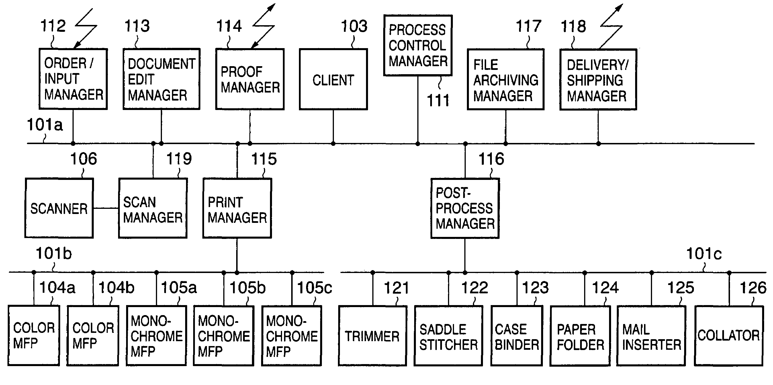
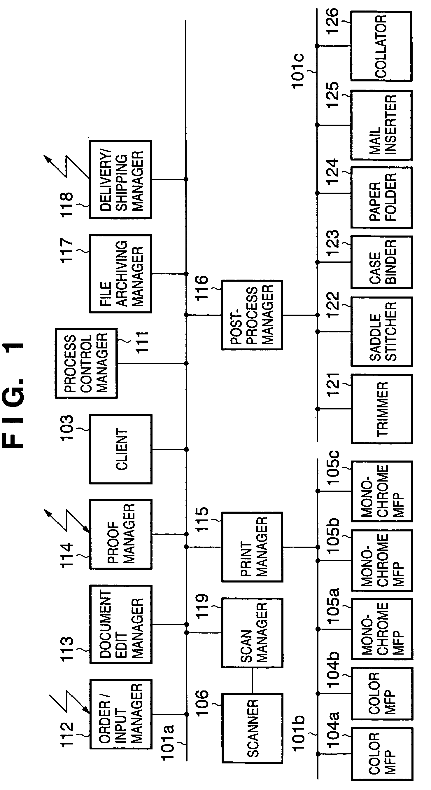
[0082]FIG. 1 is a block diagram showing an example of the arrangement of an image forming system according to the first embodiment of the present invention.

[0083]As shown in FIG. 1, respective devices which form the image forming system of this embodiment are connected via a network 101. The system may have only one network 101, or a plurality of networks 101a, 101b, and 101c, as shown in FIG. 1.

[0084]This system comprises multi-function devices such as a color MFP 104, monochrome MFP 105, and the like, which can print digital data from a scanner unit or an external device such as a computer or the like, and have a plurality of functions. Also, the system comprises single-function devices such as a scanner 106 having only a scanner function, a device (not shown) having only a print function, and the like.

[0085]This system comprises vari...

second embodiment

[0279]The first embodiment has exemplified generation of thumbnails and PDF data as proof expression methods that can be designated (selected) by the user, as shown in FIGS. 6 and 29. However, in case of a color print, an actual print allows accurate confirmation of color appearance and the like (an image on the screen often has color appearance slightly different from an actual print due to the characteristics of a display device or the like). Hence, as a proof expression method, the print manager 114 and image forming device such as the MFP 104 (or 105) may be actually used to form only a copy of test prints (proof prints) of the designated number of copies, and that output sample may be delivered to the customer by mail, visiting with that sample, or other delivery means except for on-line means. The customer who received the output sample may confirm the proof result. Such embodiment will be described below.

Job Order Window (Proof)

[0280]FIG. 37 shows an example of a job order w...

third embodiment

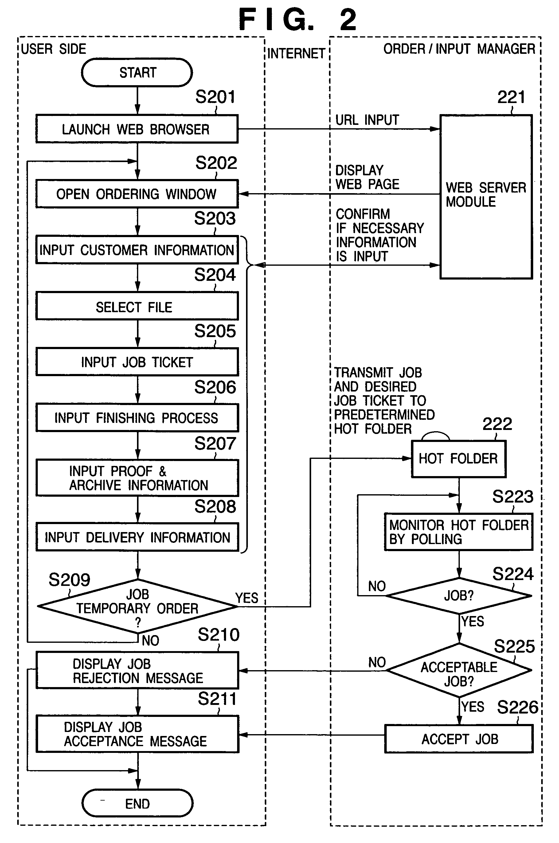
[0288]In the arrangement of the first and second embodiments, the user receives an acceptance (or rejection) message of a temporary order on the Web (steps S210 and S211 in FIG. 2). However, since the arrangement that informs an acceptance (or rejection) message of a temporary order on the Web cannot leave a confirmation record, an acceptance (or rejection) message of a temporary order may be sent by e-mail. Such embodiment will be described below.

[0289]FIG. 39 is a flow chart showing data communications between the order / input manager 112 and user's computer, and the order process (the fourth control process of the present invention) by the order / input manager 112 in the third embodiment of the present invention. In FIG. 39, S201 to S209, S3101, and S3102 indicate operation steps on the user's Web browser, and S223 to S226, S3121, and S3122 indicate control process steps on the order / input manager 112 side. Note that the same step numbers denote the same steps as in FIG. 2, and a d...


PUM


Abstract

In order to implement and manage an optimal system in the printing business and POD market, in an image forming system which comprises a plurality of devices including at least one of an image forming device which can print data in a storage unit that can store data of a plurality of jobs including data of a first job and data of a second job which is input after the data of the first job, and a sheet processing device which can execute a sheet process for a sheet printed by the image forming device, a schedule associated with a plurality of work flows including a first work flow that includes a plurality of process steps using a plurality of devices of the image forming system required to complete the first job, and a second work flow that includes a plurality of process steps using a plurality of devices of the image forming system required to complete the second job can be set.

Description

FIELD OF THE INVENTION[0001]The present invention relates to, for example, control of an image forming system which can implement an image forming process including a plurality of steps.BACKGROUND OF THE INVENTION[0002]Conventionally, a so-called commercial printing business, that receives an order of a creation request of prints (magazine, newspaper, brochure, advertisement, gravure, etc.) from a third party (customer, client), creates prints desired by the client, and delivers them to the client so as to get a reward, still prevalently uses a large-scale printing device such as an offset prepress & printing press and the like today. Such printing business proceeds with operations via various steps such as document acceptance, design & layout, comprehensive layout (presentation by means of printer output), proofing (layout correction & color correction), proof print, artwork preparation, print, post-process, shipping, and the like. Artwork preparation is mandatory for use of the af...

Claims


Application Information

Patent Timeline
Patent Type & Authority Patents(United States)
IPC IPC(8): G06F15/00G06F15/173G06F3/12G06F17/00
CPCG06F3/1205G06F3/1285G06F3/1275G06F3/1256
Inventor TAKAHASHI, HIROYUKINAGASHIMA, NAOUSHIYAMA, KAZUHIKO
Owner CANON KK
Learn More