Solar modules with tracking and concentrating features

a solar module and solar concentrator technology, applied in the field of solar modules, can solve the problems of difficult installation of sun tracking panels on residential rooftops, incompatibility of solar concentrator systems of the day, and thin solar cell modules of flat panel applications, so as to reduce the number of solar cells needed and enhance photovoltaic efficiency

Inactive Publication Date: 2009-08-04
INTEMATIX
View PDF10 Cites 28 Cited by
  • Summary
  • Abstract
  • Description
  • Claims
  • Application Information

AI Technical Summary

Benefits of technology

[0015]Embodiments of the present invention are directed to a solar module packaging and assembly of a plurality of linear solar concentrators, the solar module and concentrator assembly system capable of converting solar energy into electricity. The assembly can be embedded in a sealed structure that is similar in dimensions to conventional terrestrial weather-proofed modules. Each individual linear concentrator can possess a freedom of axial rotation while being sealed inside the fixed structure, the axial rotation providing the mechanics to realize solar tracking collectively for an array of concentrator assemblies. With such an arrangement, the frame holding the concentrator array can remain stationary, so space does not need to be dedicated to pivoting or the frame. The solar module can be constructed in such a way that sun tracking solar concentrators can be pivotably mounted and enclosed inside the module to reduce the number of solar cells needed, while simultaneously enhancing photovoltaic efficiency in a module configured as a fixed flat-panel structure. The concentrator assemblies used in the array can be composed of optical elements and solar irradiation receivers for converting solar energy into electricity.
[0018]The solar assembly tracking mechanism can include, e.g., an array of light detectors that provide a first pattern of detector signals when the concentrator aperture normals are aligned with the sun and a second different pattern of detector signals when the normals are not aligned with the sun. The different pattern can be interpreted according to a defined algorithm to determine the relative angle and direction the module must be turned to provide alignment with the sun. In particular embodiments, power used to drive the tracking mechanism adjustments can be derived from one or more non-concentrated, flat-plate solar cells. In this way, power can be provided to tracking motors even when the concentrators are not aligned with the sun.
[0019]Energy conversion efficiency of the solar modules can be enhanced by including both photovoltaic and thermoelectric receivers in a hybrid system. For example, the array of receivers can be configured with the photovoltaic receivers mounted in thermoconductive contact with the thermoelectric receivers so that the photovoltaic receivers can convert usable light into electricity while the thermoelectric receivers cool the system and convert heat to additional electricity. Alternately, the solar modules can include devices to refract and direct long wavelengths to thermoelectric receivers while allowing usable visible and UV frequencies to strike photovoltaic receivers. For example, the concentrator assemblies can include a prism, diffraction grating or optical band pass filter to direct visible light to the photovoltaic receiver array and to direct infrared light to the array of thermoelectric receivers.
[0020]The invention includes methods and systems to remove excess heat from modules to reduce thermal stresses and to enhance the efficiency of the solar receivers. In a basic embodiment, the backing plate of the module can act as a heat sink in thermal conductive contact with the array of receivers to remove heat during operation. In embodiments wherein more rapid heat removal is desired, the solar module can include a coolant fluid in a conduit mounted in thermoconductive contact with the photovoltaic receivers and / or the thermoelectric receivers. The coolant can optionally flow in a coolant loop, e.g., to an external heat exchanger to release heat from the solar module into ambient air.
[0024]In an embodiment of systems of the invention with moisture abatement capabilities, a vent channel between the trap and external environment can be long and thin (e.g., 6 inches, 12 inches, 24 inches or more long, and 1 mm, 0.5 mm, 0.25 mm or less internal diameter) to reduce the intrusion of water vapor into the water trap by diffusion. It is preferred embodiment, the vent channel is coiled to make it more compact. For example, a solar concentrator system with moisture abatement capability can include a sealed solar concentrator module having a channel fluidly connecting an internal space of the module to an external environment through a water vapor trap, and the channel between the vapor trap and the external environment can include a coiled tube with an internal diameter of less than 0.5 mm. In preferred embodiments of water abatement methods, the water trap can be heated at appropriate times. For example, the invention includes methods of abating condensation inside solar concentrator module by providing a channel fluidly connecting an internal space of the module to an external environment through a water vapor trap, and heating the vapor trap when air is flowing from the interior space to the external environment.DEFINITIONS

Problems solved by technology

Today's solar concentrator systems are generally not compatible with flat-panel modules adapted for residential rooftop installation.
There are two apparent drawbacks to these prior art approaches when applied to residential roof top installations.
Second, most concentrator optics need to be large in size to achieve a high degree of concentration and, therefore, are inappropriate for a flat panel applications having thin solar cell modules.
Sun tracking panels are difficult to install on residential rooftops, and current tracking mechanisms which move the entire module frame are bulky and expensive to maintain.
However, this can create space between collectors where no light can be collected.
It is obvious that a large spacing between concentrators, g, wastes useful solar irradiance because a certain part of photon flux from the sunlight (proportional to the spacing dimension) is not collected.
While the prior art provides parameters that should be optimized for particular situations, it does not provide satisfactory solutions.

Method used


Image

  • Solar modules with tracking and concentrating features
  • Solar modules with tracking and concentrating features
  • Solar modules with tracking and concentrating features

Examples


Embodiment Construction

[0055]The present inventions provide combinations of features useful in increasing the efficiency and lowering the cost of power production from sunlight. Systems of the invention provide mechanical and optical components that can optimize capture of sunlight for all seasons and times of day in a relatively thin and stationary module. Systems of the invention can include arrays of photovoltaic cells disposed to each receive appropriate frequencies of the incoming spectrum through devices of the invention. Efficiencies can be further improved by providing thermoelectric devices in the systems to generate voltages from waste heat, cooling components to enhance the efficiency of the voltaic components, and vapor entrapment systems to prevent fogging of optic components.

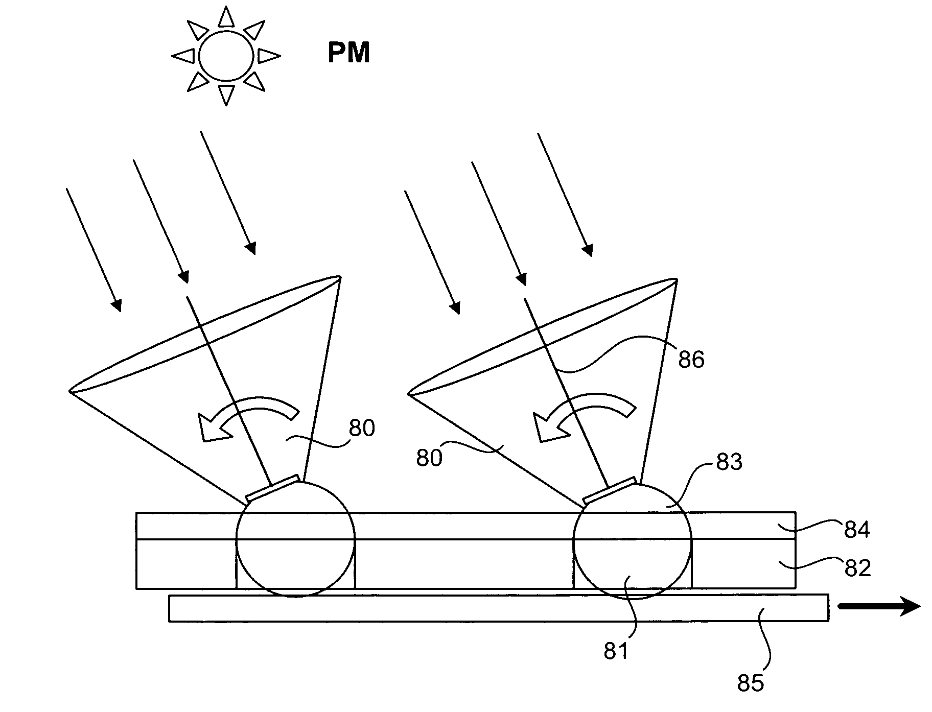
[0056]Solar-electric systems of the invention provide devices to efficiently convert solar rays and / or heat to electrical power. Tracking systems are provided to follow the sun with concentrators with one or two degrees ...


PUM


Abstract

Disclosed are fixed solar-electric modules having arrays of solar concentrator assemblies capable of separately tracking movements through one or two degrees of rotational freedom to follow the movement of the sun daily and / or seasonally. The concentrators can include optical elements to direct and concentrate light onto photovoltaic and / or thermoelectric receivers for generation of electric current.

Description

CROSS-REFERENCE TO RELATED APPLICATIONS[0001]This application claims priority to and benefit of prior U.S. Provisional Application Nos.: 60 / 762,298, Solar Module with Embedded Concentrator Assembly, filed Jan. 25, 2006; 60 / 789,427, Solar Module and Concentrator Assembly with Cooling Means, filed Apr. 4, 2006; 60 / 787,932, Collective 2-D Tracking System for Solar Module with Embedded Concentrator Assembly, filed Mar. 31, 2006; 60 / 830,387, Solar Module with Embedded Concentrator Assembly, filed Jul. 11, 2006; and, 60 / 838,943, Moisture Abatement in Solar Concentrator Modules, filed Aug. 18, 2006. The full disclosure of the prior applications are incorporated herein by reference.FIELD OF THE INVENTION[0002]Embodiments of the present invention are directed in general to tracking systems for photovoltaic and thermoelectric solar modules and combinations of such technologies that efficiently convert solar energy directly into electrical energy. In particular, the embodiments are directed to...

Claims


Application Information

Patent Timeline
Patent Type & Authority Patents(United States)
IPC IPC(8): H01L31/052F24S50/20
CPCF24J2/08H01L31/0547F24J2/38F24J2/4612F24J2/4618F24J2/5431H01L31/052H01L35/30H02S40/44F24J2/1047F24J2002/0084F24J2002/1023F24J2002/108F24J2002/5468Y02E10/47Y02E10/52Y02E10/60H02S20/32H01L31/0543F24S23/80F24S30/48F24S2020/16F24S50/20F24S2023/834F24S2023/872F24S40/40F24S40/42F24S23/30F24S2030/136H10N10/13
Inventor SHAN, WEIWANG, GANGXIANG, XIAO DONG
Owner INTEMATIX
Why Eureka
Try Eureka