Deflection signal compensation for charged particle beam

a charge particle and beam technology, applied in the field of charge particle beam systems, can solve the problems of not receiving the correct force to deflect the charge particle to either the first or the second dwell point, and it is impossible to precisely process the work piece, so as to improve the ability of the charge particle beam system, improve beam control, and improve the effect of precision

Active Publication Date: 2009-08-04
FEI CO
View PDF8 Cites 18 Cited by
  • Summary
  • Abstract
  • Description
  • Claims
  • Application Information

AI Technical Summary

Benefits of technology

[0011]An object of the invention is to improve the ability of charged particle beam systems to precisely direct particles to a work piece.
[0013]The invention compensates for the time required for the charged particles to traverse the system by altering one or more of the deflector signals. According to one embodiment of the invention, signals applied to the stages of a multiple stage deflector system are applied independently, for example, at different times, to more closely align the deflection signals with the flight of the particles through the deflection system so fewer particles are misdirected. For example, in a two stage deflection system, a change to the second stage deflector voltage may be delayed with respect to the change to the first stage deflector voltage. The delay provides improved beam control and allows for precise processing even at reduced dwell time.

Problems solved by technology

For example, when a signal applied to a deflector system is changed to direct the beam from a first dwell point to a second dwell point, charged particles that have already passed through part of the deflection system when the voltage is changed will not receive the correct forces to deflect them to either the first or the second dwell point.
As dwell periods become shorter, voltage changes become more frequent, and the number of particles that are traversing the deflection system during voltages change increases, so more particles are misdirected, making it impossible to precisely process a work piece.

Method used


Image

  • Deflection signal compensation for charged particle beam
  • Deflection signal compensation for charged particle beam
  • Deflection signal compensation for charged particle beam

Examples


Embodiment Construction

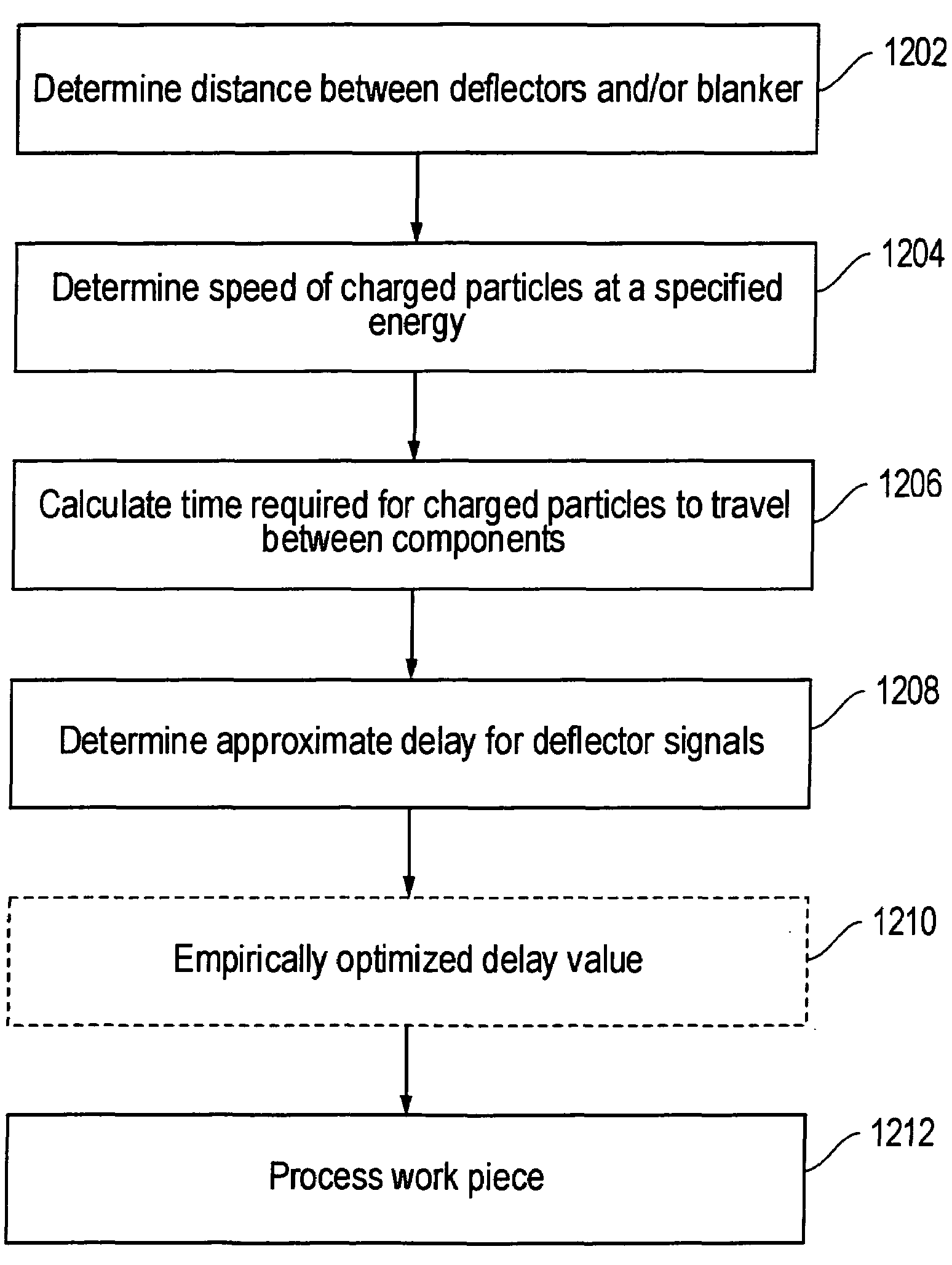
[0027]The invention facilitates precise delivery of charged particles in a charged particle beam system having a directable beam, and is particularly useful when the system is changing the beam position rapidly, that is, when using short dwell times.

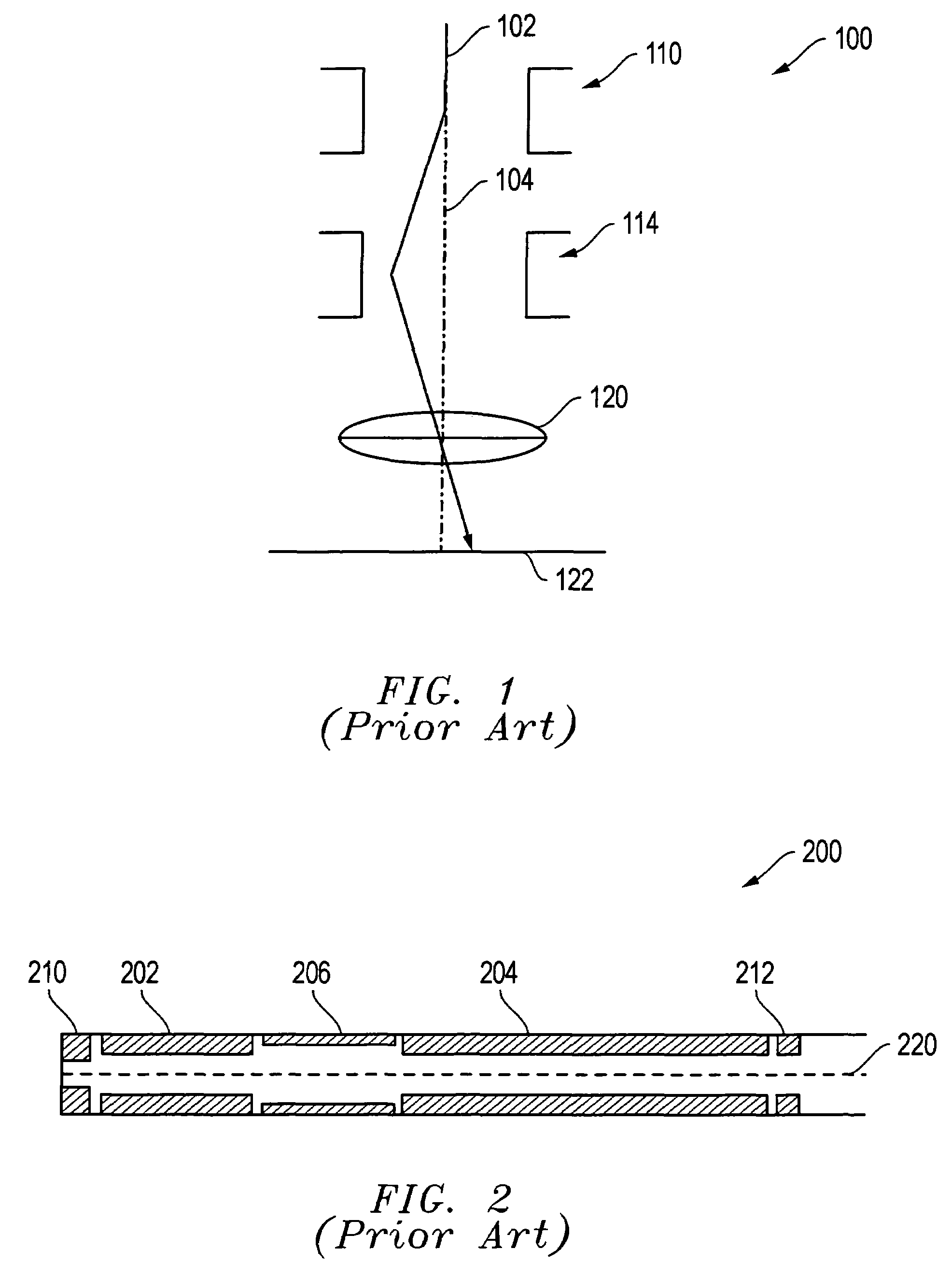
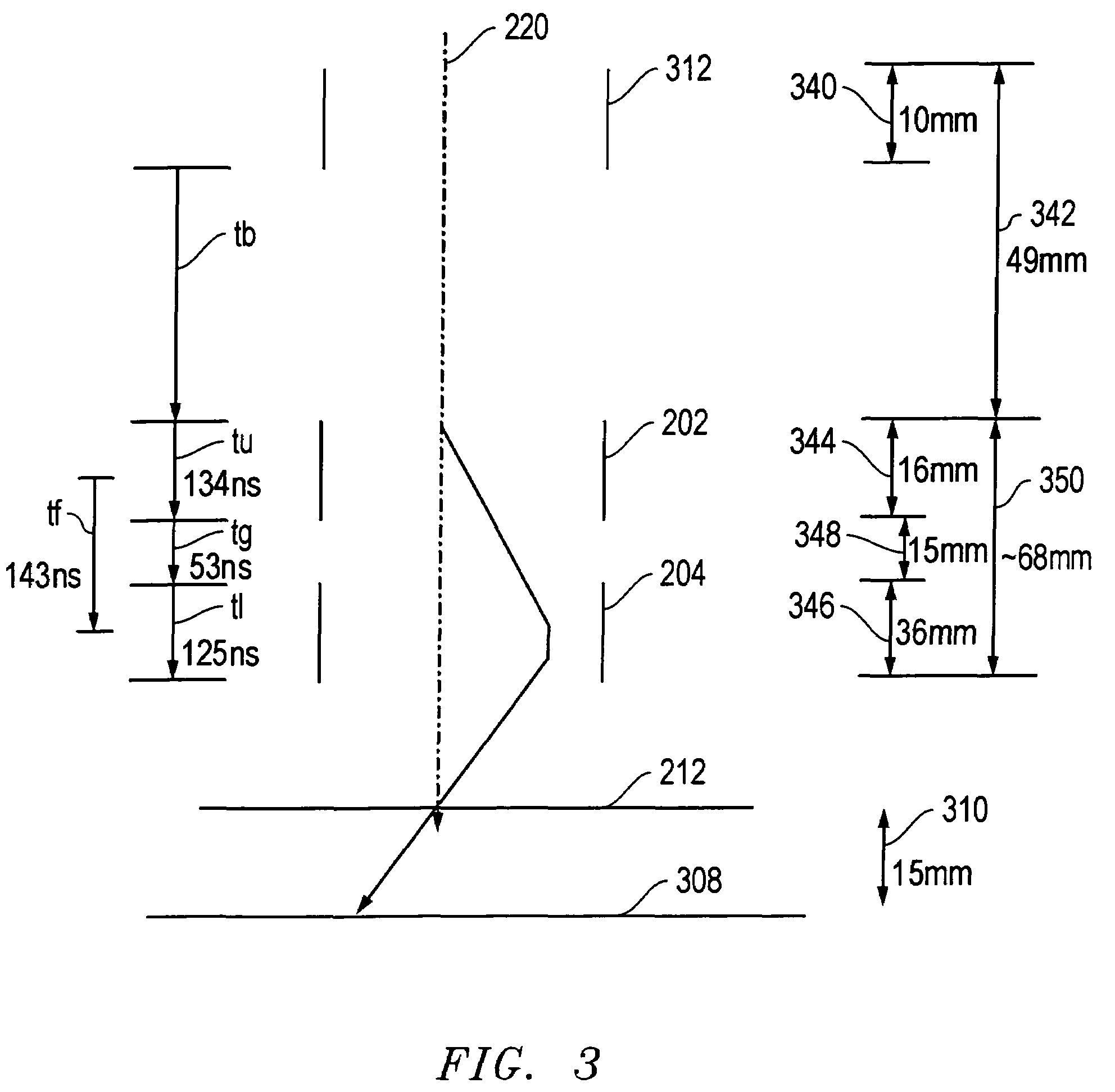
[0028]In a typical high performance charged particle beam optical column, a dual stage deflection system is used to control the position of the particle beam on the work piece. Each stage of the deflection system imparts an appropriate deflection to the beam as it passes. The two stages work together to ensure the beam follows the correct path through the column and the particles impact the work piece at the desired point. The amount of deflection in each stage is determined by electrical signals that apply voltages to the deflector plates in that stage. By varying the voltages on the plates, the electrical fields through which the charged particles pass are varied, which changes the force on the particles and therefore their landing pos...


PUM


Abstract

Charged particles that are in transit through a deflection system when the beam is repositioned do not received the correct deflection force and are misdirected. By independently applying signals to the multiple stages of a deflection system, the number of misdirected particles during a pixel change is reduced.

Description

[0001]This application claims priority from U.S. Prov. Pat. App. 60 / 680,660 filed May 14, 2005, which is hereby incorporated by reference.TECHNICAL FIELD OF THE INVENTION[0002]The present invention relates to charged particle beam systems, such as focused ion beam systems and electron beam systems.BACKGROUND OF THE INVENTION[0003]Charged particle beams, such as focused ion beam systems and electron beam systems, direct charged particles onto a work piece for processing the work piece or for forming an image of the work piece. Charged particle beam systems are used, for example, in integrated circuit fabrication and other nanotechnology processing. Charged particles beam systems typically include a source of particles, a beam blanker, accelerating lenses, focusing optics, and deflection optics.[0004]A charged particle source may be, for example, a liquid metal ion source, a plasma ion source, or a thermal field electron emitter, such as a Schottky emitter. A beam blanker interrupts t...

Claims


Application Information

Patent Timeline
Patent Type & Authority Patents(United States)
IPC IPC(8): A61N5/00G21G5/00
CPCH01J37/1474H01J37/1477H01J37/28H01J37/302H01J37/3056H01J37/304H01J2237/30483H01J2237/1516H01J2237/30461
Inventor HILL, RAYMONDROSENBERG, STEVE AKEDOWNER, DANIEL B.
Owner FEI CO
Why Eureka
Try Eureka