
Exhaust gas purification apparatus of engine

a technology of exhaust gas purification and exhaust gas, which is applied in mechanical equipment, machines/engines, separation processes, etc., can solve the problems of clogging of nozzles, nozzles evaporate, exhaust gases are exhausted into the atmosphere without being sufficiently reduced and purified, and achieve the effect of preventing clogging of nozzles

Active Publication Date: 2009-08-11
VOLVO TRUCK CORP
View PDF17 Cites 17 Cited by
  • Summary
  • Abstract
  • Description
  • Claims
  • Application Information

AI Technical Summary

Benefits of technology

Prevents nozzle clogging and ensures sufficient supply of the liquid reducing agent to the NOx reduction catalyst, maintaining effective NOx reduction and purification by using high pressure air to clear the nozzle of residual liquid reducing agent.

Problems solved by technology

In such an exhaust gas purification apparatus, when the nozzle is at a high temperature due to the exhaust heat, and the injection supply of the liquid reducing agent is stopped, there is a possibility that water content from the liquid reducing agent remaining inside the nozzle evaporates, and reducing agent constituents are deposited and become attached to the inside of the nozzle, thus causing it to become clogged.
If clogging occurs in the nozzle, then even though injection supply of the liquid reducing agent is restarted afterwards, there is concern that liquid reducing agent of a necessary amount corresponding to the engine operating conditions is not supplied to the NOx reduction catalyst, and the NOx in the exhaust is exhausted into the atmosphere without being sufficiently reduced and purified.

Method used


Image

  • Exhaust gas purification apparatus of engine
  • Exhaust gas purification apparatus of engine
  • Exhaust gas purification apparatus of engine

Examples


first embodiment

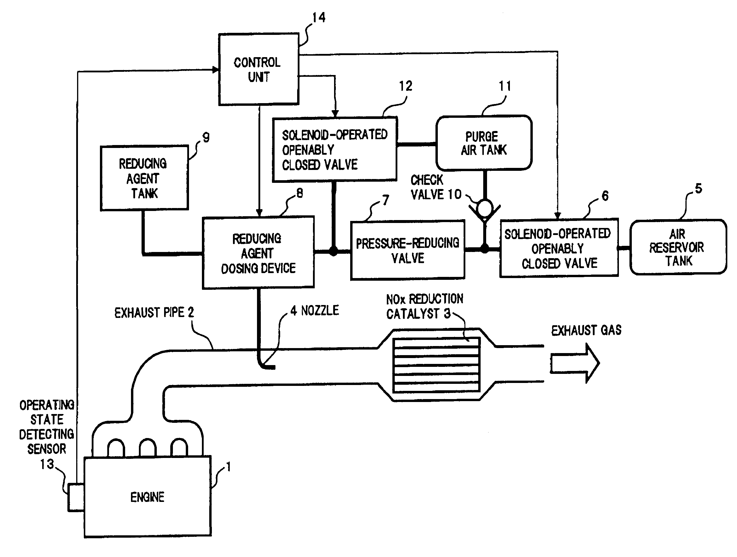
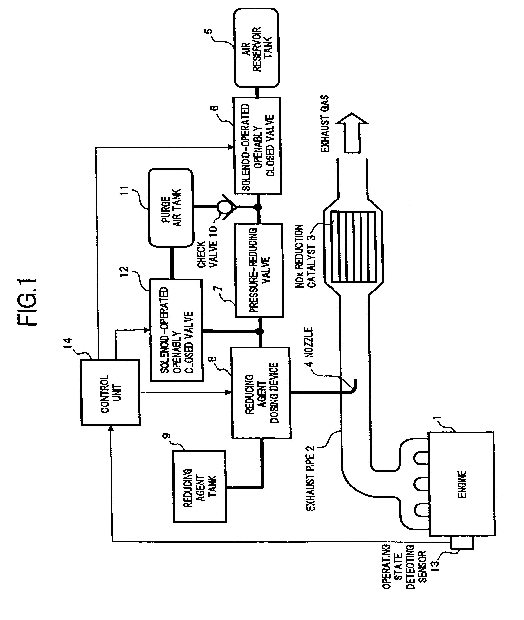
[0015]FIG. 1 shows the overall construction of an exhaust gas purification apparatus according to the present invention.

[0016]Referring to FIG. 1, a NOx reduction catalyst 3 for reducing and purifying the NOx in an exhaust gas is provided in an exhaust pipe 2 constituting an exhaust gas passage of an engine 1. The NOx reduction catalyst 3 is of a construction where for example a zeolite type active ingredient, is supported by a monolithic type catalyst support having a honeycomb shaped cross-section comprising ceramic cordierite, or an Fe—Cr—Al type heat-resistant steel. Moreover, the catalyst ingredient supported by the catalyst support, receives a supply of a liquid reducing agent such as a urea water solution, gasoline, a diesel oil, alcohol or the like, and is activated, to thereby effectively convert the NOx into a harmless substance.

[0017]A nozzle 4 is provided on the exhaust gas upstream side of the NOx reduction catalyst 3, to injection-supply a liquid reducing agent from an...

third embodiment

[0030]FIG. 3 shows the overall construction of an exhaust gas purification apparatus according to the present invention.

[0031]In the present embodiment, a construction is adopted in which, instead of the pressure-reducing valve 7 in the first and second embodiments, a pressure reducing valve 30 is provided that can be switched to either let compressed air stored in the air reservoir tank 5 pass through directly, or to reduce the pressure to a predetermined pressure as it passes through, and the switching is controlled by a control unit 14.

[0032]The control unit 14 opens a solenoid-operated openably closed valve 6 when the liquid reducing agent is injection-supplied, and controls the switching of the pressure-reducing valve 30 so as to reduce the pressure of the compressed air. Furthermore, the control unit 14 opens the solenoid-operated openably closed valve 6 for a predetermined period after injection of the liquid reducing agent is stopped, and also controls the switching of the p...

fourth embodiment

[0034]FIG. 4 shows the overall construction of an exhaust gas purification apparatus according to the present invention.

[0035]In the present embodiment, a construction is adopted in which, when a liquid reducing agent is injection-supplied, compressed air is not used, but the liquid reducing agent is pressurized by a reducing agent dosing device 40, for injection supply.

[0036]According to such a construction, since it is not necessary to supply compressed air from the air reservoir tank to the reducing agent dosing device, as in the previous first to third embodiments, the number of solenoid-operated openably closed valves is reduced, and also a pressure-reducing valve is not required, and hence the space and cost can be reduced. Furthermore, since compressed air for dosing the reducing agent is not required, there is no need to increase the size of the air reservoir tank provided for other purposes.

[0037]As described above, in an exhaust gas purification apparatus according to the ...


PUM


Abstract

A liquid reducing agent of a necessary amount according to an engine operating condition is injection-supplied from a nozzle having an injection hole opening to inside an exhaust gas passage, positioned on an exhaust gas upstream side of a nitrogen oxide reduction catalyst. On the other hand, when an injection flow rate of the liquid reducing agent becomes zero, compressed air stored in a purge air tank is supplied into the nozzle for a predetermined time. Thus, the liquid reducing agent remaining in the nozzle is forcibly discharged by the compressed air, and hence even if the nozzle is at a high temperature due to the exhaust heat, a situation where reducing agent constituents are deposited does not occur, and clogging of the inside of the nozzle can be prevented.

Description

[0001]This is a U.S. National Stage of PCT / JP2004 / 010487, filed on Jul. 23, 2004.BACKGROUND OF THE INVENTION[0002]1. Field of the Invention[0003]The present invention relates to an exhaust gas purification apparatus of an engine (referred to hereunder as “exhaust gas purification apparatus”), which reduces the nitrogen oxide (NOx) in the exhaust gas using a liquid reducing agent. In particular, it relates to technology for preventing a failure in the reduction and purification of NOx.[0004]2. Description of the Related Art[0005]As an exhaust gas purification apparatus for removing NOx contained in engine exhaust gas, a type disclosed in Japanese Unexamined Patent Publication No. 2000-27627 has been proposed. In such an exhaust gas purification apparatus, a NOx reduction catalyst is arranged in an engine exhaust gas passage in order to convert NOx into harmless nitrogen (N2) and oxygen (O2) in an oxygenated atmosphere filled with excessive amount of oxygen. Furthermore, a constructio...

Claims


Application Information

Patent Timeline
Patent Type & Authority Patents(United States)
IPC IPC(8): F01N3/00F01N3/08B01D53/90B01D53/94F01N3/20F01N3/28
CPCB01D53/90B01D53/9495F01N3/2066Y02T10/24F01N2610/08F01N2610/1493F01N2900/08F01N2610/02Y02T10/12
Inventor HIRATA, KIMINOBU
Owner VOLVO TRUCK CORP
Learn More