Operational amplifier of class AB

an operation amplifier and amplifier technology, applied in amplifiers, amplifiers with semiconductor devices/discharge tubes, electric devices, etc., can solve the problems of poor behavior with large signals, complex mixed-signal integrated circuits, and even more critical power consumption optimization, so as to reduce power consumption and enhance dc-gain

Active Publication Date: 2009-08-18
STMICROELECTRONICS SRL
View PDF4 Cites 16 Cited by
  • Summary
  • Abstract
  • Description
  • Claims
  • Application Information

AI Technical Summary

Benefits of technology

[0015]An object of the present invention is to overcome the limits which affect the known amplifiers and to provide an operational amplifier based on the adaptive bias principle that has structural and functional characteristics which allow reduced power consumption and, at the same time, enhanced DC-gain.
[0016]One embodiment of the present invention provides an operational amplifier having a fully symmetrical core, preferably of the OTA type in order to reduce power consumption, connected to an adaptive bias block that implements the adaptive bias principle, preferably comprising a positive feedback biasing block in order to enhance the DC-gain of the operational amplifier.

Problems solved by technology

As is well known, the increased complexity of mixed-signal Integrated Circuits (or IC's) makes it crucial to optimize their power consumption.
Moreover, the current market for IC's requires more and more a shift toward low voltage applications, making power consumption optimization even more critical.
Class A op-amps have poor behavior with large signals due to their constant tail current, and thus they show a transient response that is slew-rate limited, as described by Klinke et al. in the article entitled “A Very-High-Slew-Rate CMOS Operational Amplifier” (IEEE Journal of Solid-State Circuits, vol.
However, such a circuit has a maximum output current which is not well controlled; this could be a problem in low-power applications, especially where a portable system with a battery aboard is concerned.
However, this known solution has a problem due to the fact that the DC-gain of the op-amp so obtained is limited, since it has just one pole at high impedance on its output node.

Method used


Image

  • Operational amplifier of class AB
  • Operational amplifier of class AB
  • Operational amplifier of class AB

Examples


Embodiment Construction

[0025]Preferred embodiments of the present invention will be described in detail hereinbelow with reference to the attached drawings.

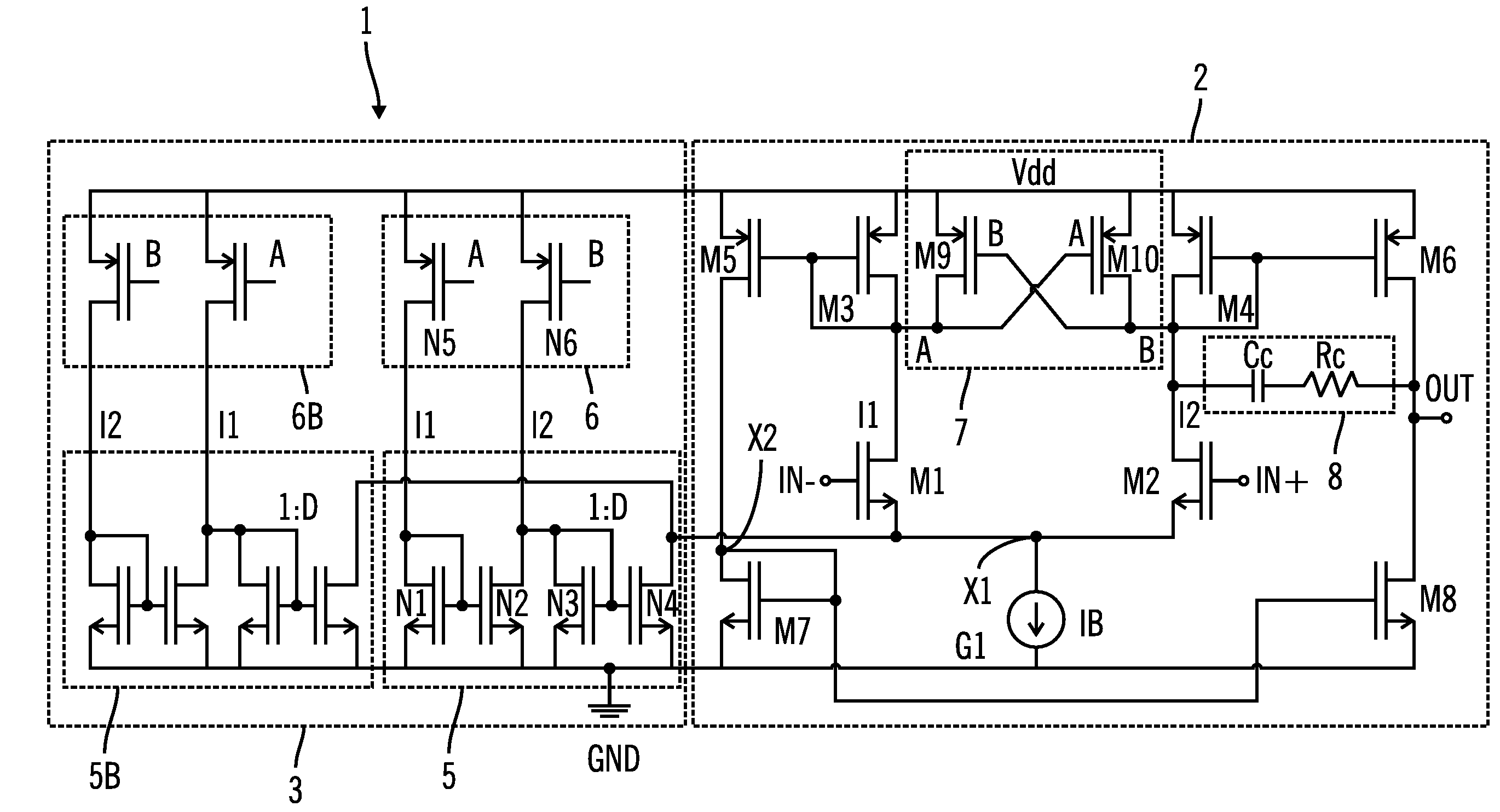
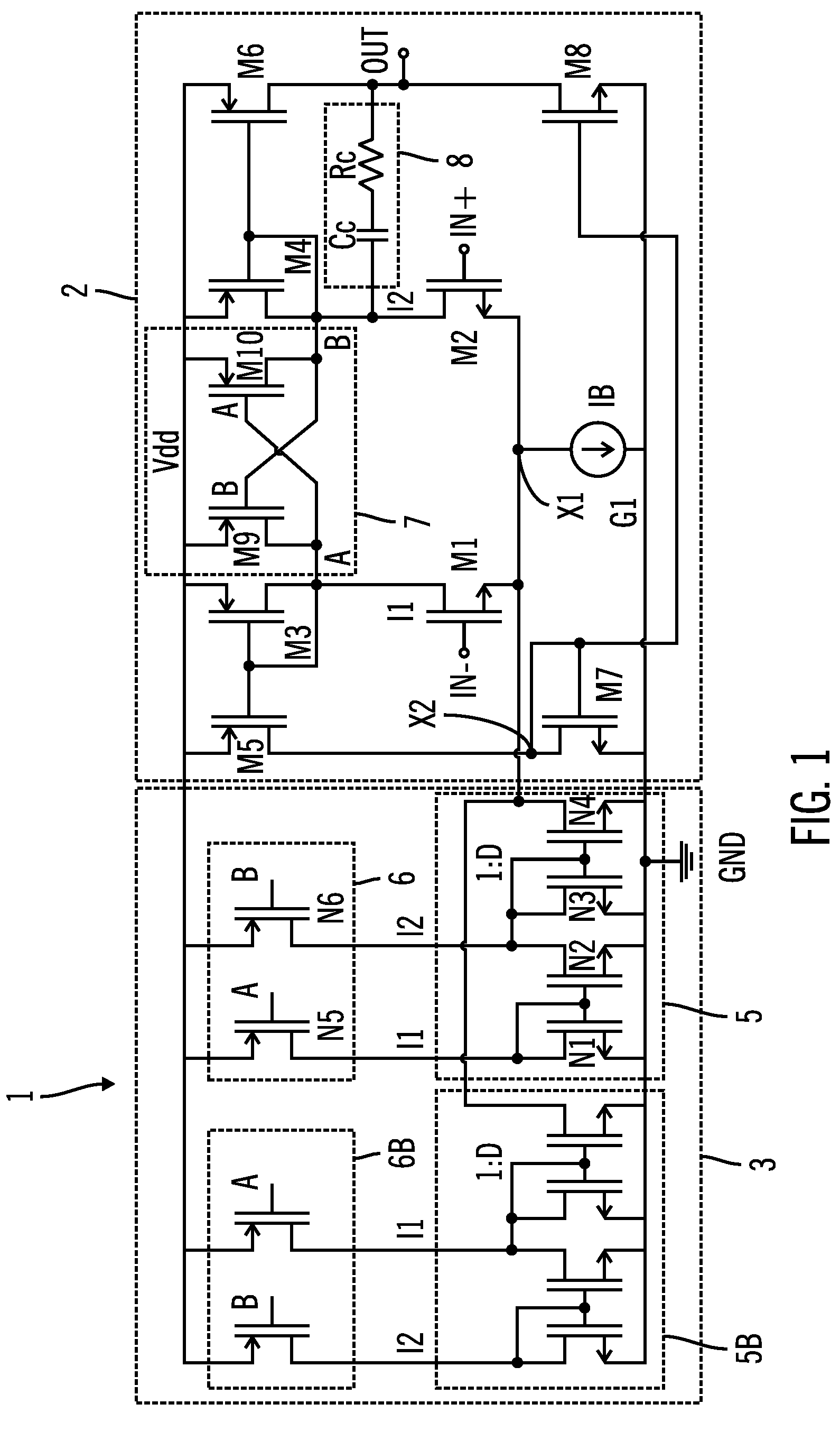
[0026]FIG. 1 shows an operational amplifier (or “op-amp”) according to a preferred embodiment of the present invention.

[0027]The op-amp 1 includes a core 2 and an adaptive bias block 3 connected between first and second voltage references, in particular a supply voltage reference Vdd and ground GND, and interconnected at a first common node X1.

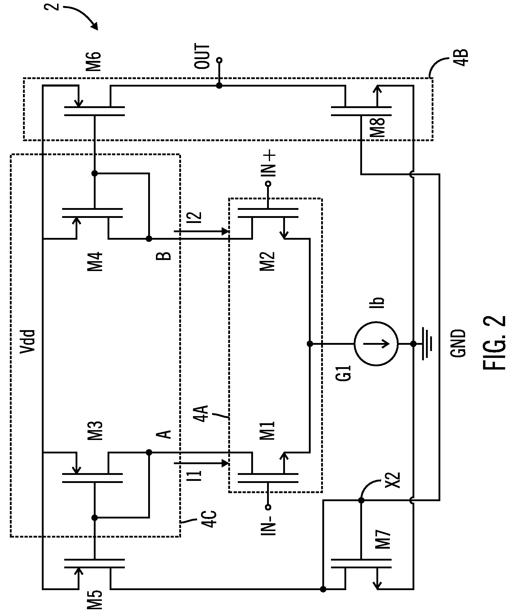
[0028]According to this embodiment of the present invention, the core 2 is realized by an OTA (Operational Transconductance Amplifier), as shown in FIG. 2. More particularly, the core 2 is a CMOS OTA with a symmetrical input stage comprising first and second input transistors M1 and M2.

[0029]These input transistors M1 and M2 are connected between respective first and second internal nodes A and B and the first common node X1, and have control (or gate) terminals respectively connected to a first input terminal IN...


PUM


Abstract

A class AB operational amplifier is provided that includes first and second input transistors respectively coupled between first and second internal nodes and a first common node, first and second input stage load transistors diode connected and respectively coupled between a first voltage reference and the first and second internal nodes, first and second output transistors coupled in series between the first voltage reference and a second voltage reference, a tail current generator coupled between the first common node and the second voltage reference, an adaptive bias block coupled between the first and second voltage references and coupled to the first common node, and a positive feedback network coupled between the first voltage reference and the first and second internal nodes. Also provided is an integrated circuit having at least one such operational amplifier.

Description

CROSS-REFERENCE TO RELATED APPLICATIONS[0001]This application is based upon and claims priority from European Patent Application No. 06 011 220.8, filed May 31, 2006, the entire disclosure of which is herein incorporated by reference.FIELD OF THE INVENTION[0002]The present invention relates to electronic circuits, and more specifically relates to a class AB operational amplifier that is suitable for low voltage applications.BACKGROUND OF THE INVENTION[0003]As is well known, the increased complexity of mixed-signal Integrated Circuits (or IC's) makes it crucial to optimize their power consumption.[0004]Moreover, the current market for IC's requires more and more a shift toward low voltage applications, making power consumption optimization even more critical.[0005]For this aim, low power architectures have to be used as building blocks of a whole IC and innovative circuit topologies have to be explored.[0006]It is also well known that the operational amplifier (or “op-amp”) is probab...

Claims


Application Information

Patent Timeline
Patent Type & Authority Patents(United States)
IPC IPC(8): H03F3/45
CPCH03F3/45183H03F2200/456H03F2200/513H03F2203/45648H03F2203/45454H03F2203/45644H03F2203/45448
Inventor DALENA, FRANCESCO MARIA
Owner STMICROELECTRONICS SRL
Why Eureka
Try Eureka