Microphone device and audio player

a microphone and audio technology, applied in the direction of transducer casings/cabinets/supports, electrical transducers, transducers, etc., can solve the problems of microphone devices, 2 cannot achieve noise suppression effects, and the microphone devices of example 1 cannot handle noise coming from a plurality of directions, etc., to achieve stable operation and high s/n ratio

Active Publication Date: 2009-08-18
PANASONIC CORP
View PDF14 Cites 40 Cited by
  • Summary
  • Abstract
  • Description
  • Claims
  • Application Information

AI Technical Summary

Benefits of technology

[0017]Therefore, an object of the present invention is to provide a microphone device capable of stably operatin...

Problems solved by technology

However, the microphone device of Example 1 does not handle noise coming from a plurality of directions.
Therefore, the microphone device of Example 2 cannot achieve a noise suppression effect until filter convergence has been completed.
Moreover, under the noisy environment, filter convergence is difficult.
Further, as with Example 1, the microphone device of Example 2 cannot handle a plurality of noise sources.
Therefore, it is impossible to performing a process of collecting sounds with a sound in a specific direction being enhanced.
In the microphone device of Example 3, however, inclusion of even a slightest amount of components of the target sound in the noise reference sound will significantly deteriorate the sound quality of the processed sound or, at worse, may cancel the target sound itself.
Still further, in the spec...

Method used


Image

  • Microphone device and audio player
  • Microphone device and audio player
  • Microphone device and audio player

Examples


embodiment 1

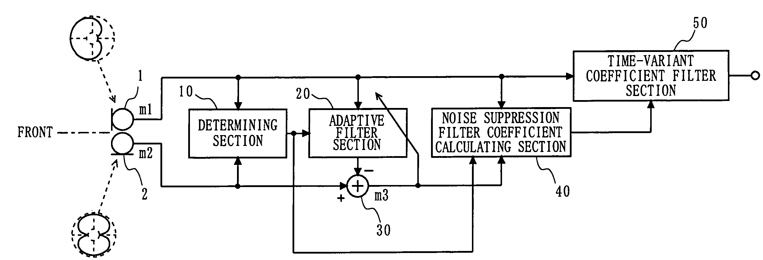
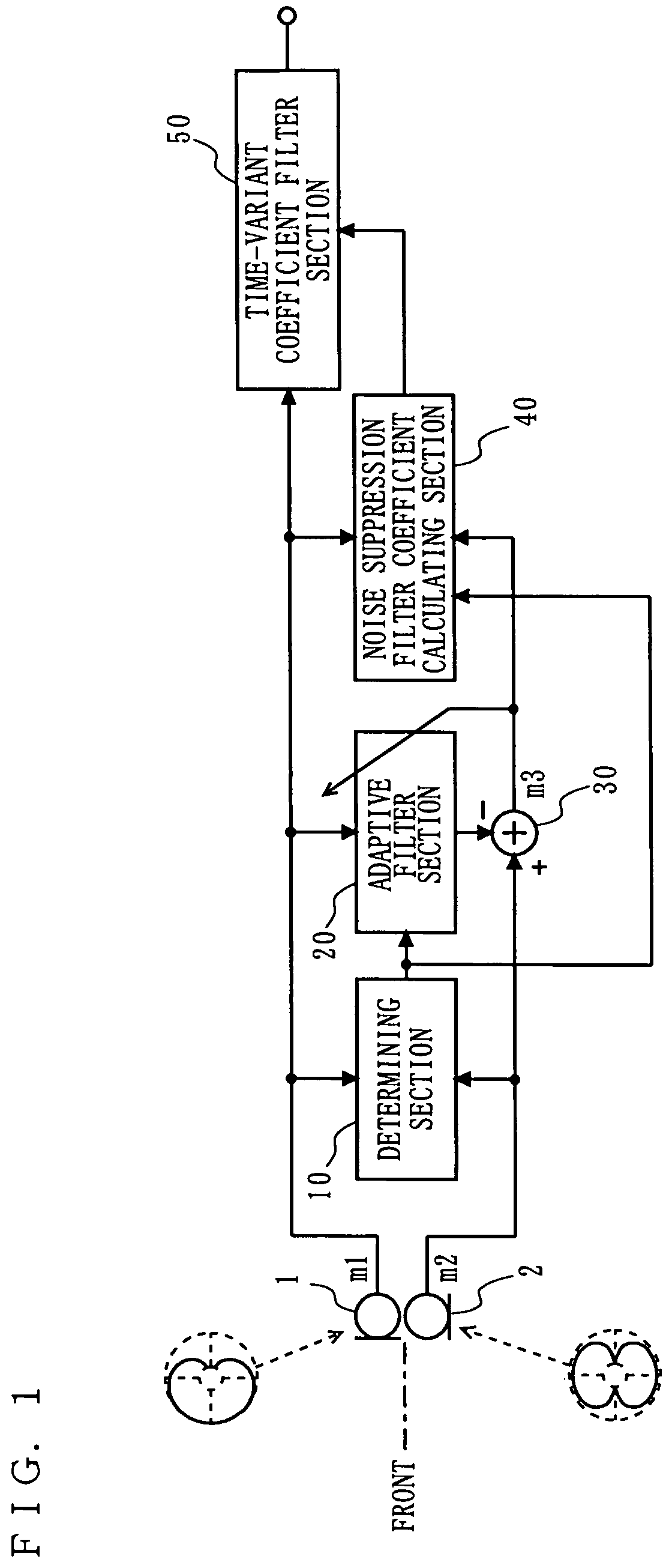
[0077]A microphone device according to Embodiment 1 of the present invention is described below with reference to FIGS. 1 through 7. FIG. 1 is a block diagram illustrating the configuration of the microphone device according to Embodiment 1. In FIG. 1, the microphone device includes a first microphone unit 1, a second microphone unit 2, a determining section 10, an adaptive filter section 20, a signal subtracting section 30, a noise suppression filter coefficient calculating section 40, and a time-variant coefficient filter 50.

[0078]In FIG. 1, the first microphone unit 1 is a unidirectional microphone unit, whose main axis of directivity is oriented to the front. The second microphone unit 2 is a bidirectional microphone unit, whose main axis of directivity is oriented so as to form a right angle with respect to the front direction. Note that the microphone device detects a sound coming from a desired direction. Hereinafter, a sound to be detected is referred to as a target sound, a...

embodiment 2

[0116]With reference to FIGS. 8 and 9, a microphone device according to Embodiment 2 is described below. In contrast of an object of the microphone device according to Embodiment 1, which is to suppress the included noise when detecting the target sound, an object of the microphone device according to Embodiment 2 is to correct distortion in frequency characteristic of the target sound caused by a detected reflected wave of the target sound.

[0117]In FIG. 8, the microphone device includes a first microphone unit 1, a second microphone unit 2, a determining section 10, an adaptive filter section 20, a signal subtracting section 30, a reflection information calculating section 60, and a reflection correcting section 70. Note that, in FIG. 8, components similar in structure to those in Embodiment 1 are provided with the same reference numerals, and are not described in detail herein.

[0118]In FIG. 8, the reflection information calculating section 60 is supplied with the filter coefficien...

embodiment 3

[0129]With reference to FIGS. 10 and 11, a microphone device according to Embodiment 3 is described below. The microphone device according to Embodiment 3 has a structure such that the structures of Embodiment 1 and 2 are combined.

[0130]FIG. 10 is a block diagram illustrating one example of the configuration of the microphone device according to Embodiment 3. In FIG. 10, the microphone device includes a first microphone unit 1, a second microphone unit 2, a determining section 10, an adaptive filter section 20, a signal subtracting section 30, a noise suppression filter coefficient calculating section 40, a time-variant coefficient filter section 50, a reflection information calculating section 60, and a reflection correcting section 70. Note that, in FIG. 10, components similar in structure to those in Embodiment 1 or 2 are provided with the same reference numerals, and are not described in detail herein.

[0131]The structure illustrated in FIG. 10 is different from that illustrated ...


PUM


Abstract

A signal generating section generates a main signal and a noise reference signal. A determining section determines whether a level ratio is larger than a predetermined value. An adaptive filter section generates a signal indicative of a signal component of a target sound included in the noise reference signal generated by the signal generating section, and learns a filter coefficient only when the determining section determines that the level ratio is larger than the predetermined value. A subtracting section subtracts the signal generated by the adaptive filter section from the noise reference signal. A noise suppressing section suppresses a signal component of noise included in the main signal by using the main signal and the noise reference signal after subtraction by the subtracting section.

Description

BACKGROUND OF THE INVENTION[0001]1. Field of the Invention[0002]The present invention relates to microphone devices and audio players and, more specifically, to a microphone device and an audio player which detects a desired sound coming from a specific direction with noise being suppressed.[0003]2. Description of the Background Art[0004]The configurations of conventional microphone devices are described with reference to FIGS. 24 through 26.[0005]FIG. 24 is an illustration showing the configuration of a conventional microphone device of Example 1. In FIG. 24, the conventional microphone device includes a first microphone unit 1010, a second microphone unit 1020, a signal adding section 1030, a first signal subtracting section 1031, a signal amplifying section 1050, an adaptive filter section 1060, and a second signal subtracting section 1062. Each of the microphone units 1010 and 1020 is placed so as to be oriented to the front (left in FIG. 24). The signal adding section 1030 adds...

Claims


Application Information

Patent Timeline
IPC IPC(8): H04B15/00H04R3/00
CPCH04R3/005H04R2410/05H04R2410/01
Inventor KANAMORI, TAKEOKAWAMURA, TAKASHIMATSUOKA, TOMOMI
Owner PANASONIC CORP
Why Eureka
Try Eureka