

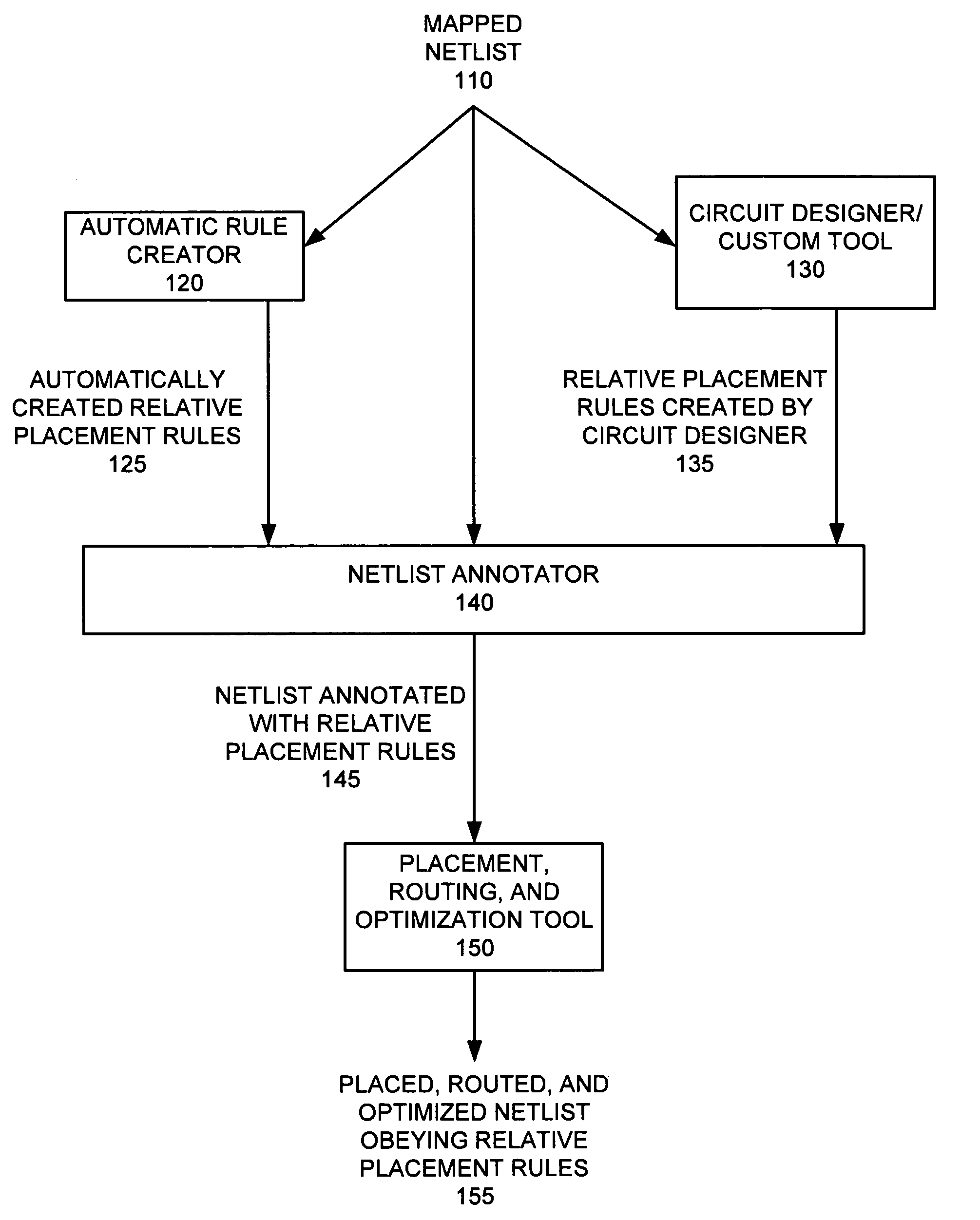
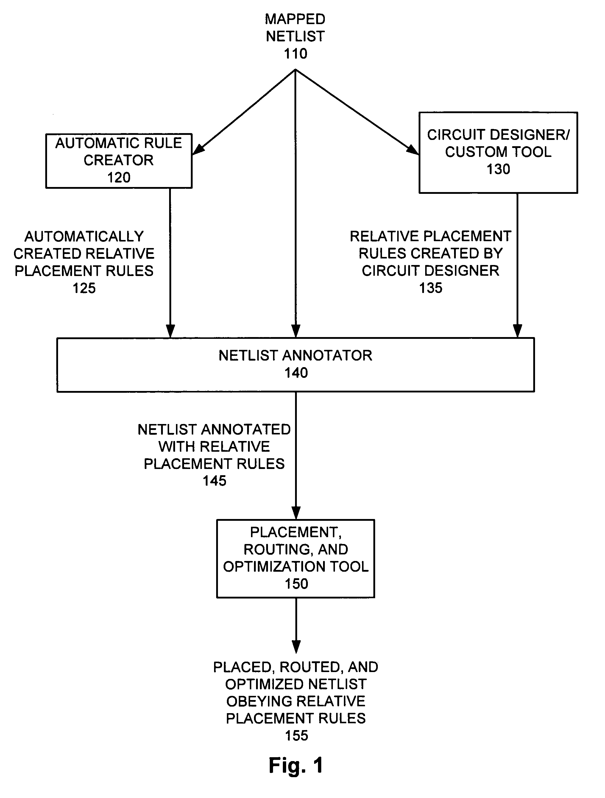
Relative positioning of circuit elements in circuit design
a technology of relative positioning and circuit elements, applied in computer aided design, program control, instruments, etc., can solve the problems of loss of structured placement requirements, affecting the design quality of integrated circuits, so as to improve the timing of the entire circuit, improve design utilization, and improve congestion
- Summary
- Abstract
- Description
- Claims
- Application Information
AI Technical Summary
Benefits of technology
Problems solved by technology
Method used
Image

Examples
example
[0422]To save all the relative placement groups to disk, remove the information from the design, then recreate the information on the design, enter[0423]psyn_shell-xg-t> find rp_group[0424]{mul::grp_mul ripple::grp_ripple example3::top_group}[0425]psyn_shell-xg-t> write_rp_group -all -output my_groups.tcl[0426]1[0427]psyn_shell-xg-t> remove_rp_group -all -quiet[0428]1[0429]psyn_shell-xg-t> find rp_group[0430]Error: Can't find objects matching ‘*’. (UID-109)[0431]psyn_shell-xg-t> source my_groups.tcl[0432]{example3::top_group}[0433]psyn_shell-xg-t> find rp_group[0434]{example3::top_group ripple::grp_ripple mul::grp_mul}
[0435]Aligning Relative Placement by Pins
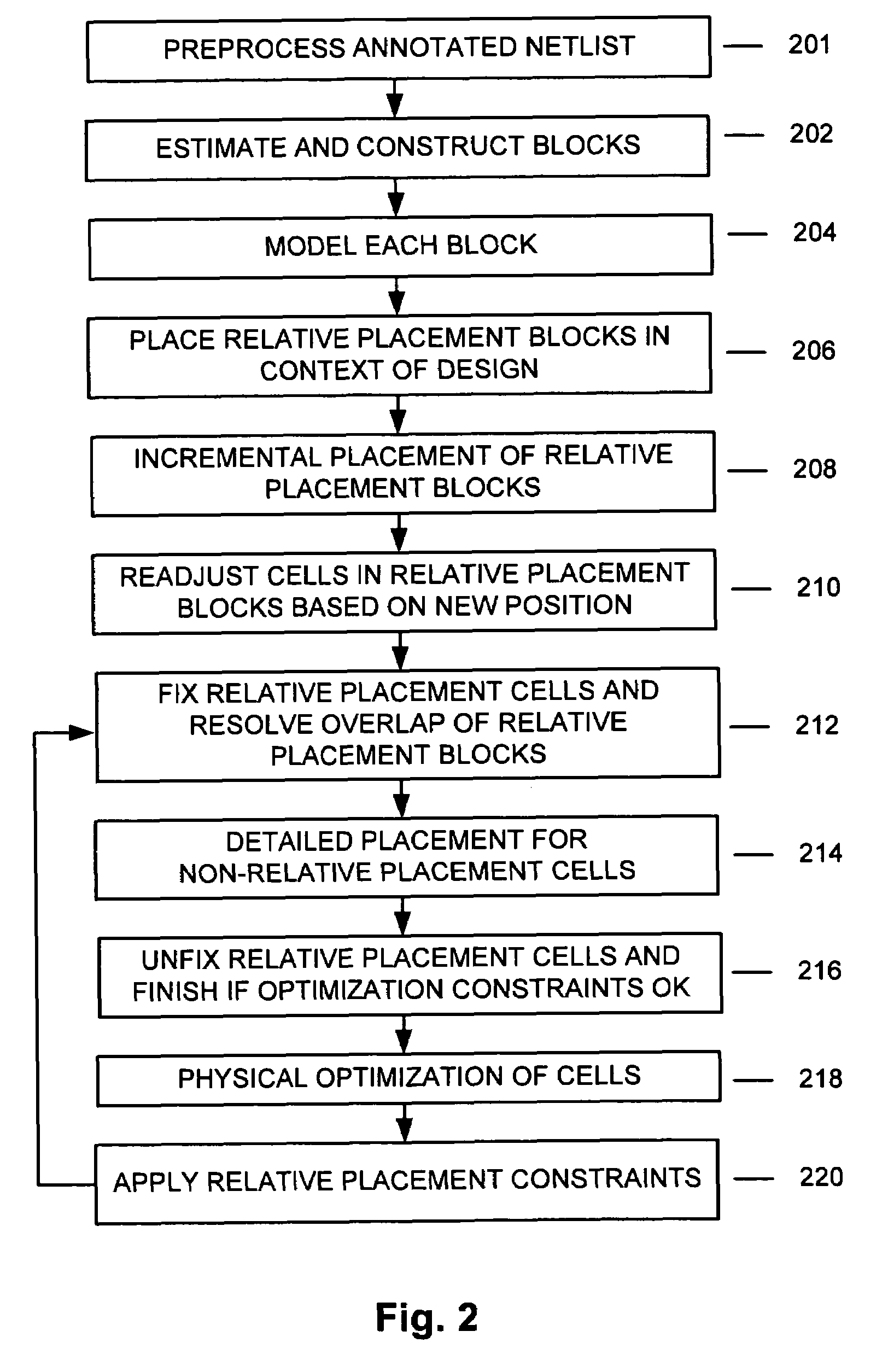
[0436]Columns can be aligned by pins instead of by the lower-left corner (the default). This capability increases the probability of straight routes and can result in less congestion, lower power, and lower routing resources by eliminating vias.
[0437]To align a group by pins, use the create_rp_group command with its -pin_align_n...
PUM
 Abstract
Description
Claims
Application Information