Method of manufacturing a composite turbomachine blade, and a blade obtained by the method

a turbomachine and composite technology, applied in the direction of wind motor components, non-positive displacement fluid engines, liquid fuel engine components, etc., can solve the problems of high cost, high cost, and damage to mechanical strength, and achieve the effect of improving cohesion and facilitating weaving

Active Publication Date: 2009-09-01
SN DETUDE & DE CONSTR DE MOTEURS DAVIATION S N E C M A
View PDF11 Cites 46 Cited by
  • Summary
  • Abstract
  • Description
  • Claims
  • Application Information

AI Technical Summary

Benefits of technology

[0012]An object of the present invention is to provide a method enabling the above-specified drawbacks to be overcome, and in particular to better conserve the integrity of the fibers after injection, and in particular after subsequent machining, by making it possible to put protector elements into place during the step of injection molding the preform.
[0023]In this way, it will be understood that by not cutting the series of tracer yarns along the reference surface, i.e. more particularly by not cutting warp yarns extending generally along the longitudinal direction of the preform, and thus of the final part, cohesion is improved, as are the mechanical properties of said reference surface. This surface can in particular be constituted by the surface of the zone of the preform that is to become all or part of the leading edge and / or the pressure-side wall and / or the root.
[0024]In addition, by subjecting the cut-out preform to pre-deformation, it is possible to ensure that the zones of the preform are properly disposed and oriented relative to one another, with this being made easier by the fact that while this is being performed, the preform obtained from the weaving and cutting-out step is relatively flexible. The deformation can be implemented in a plurality of steps, taking account of the different portions of the blade and their specific positions and orientations. Thereafter, the pre-deformed positions are frozen in step d) making relative stiffening possible by means of a compacting step because of the presence of the oiling agent that covers the yarns in order to facilitate weaving, which oiling agent may be associated with a tackifying agent, e.g. a dilute epoxy resin.
[0026]Overall, by means of the method of the present invention, it is possible to manufacture a blade, in particular a fan blade, that, on leaving the injection step, presents various portions of shape and dimensions that are very close to those of the final part.

Problems solved by technology

That technique is very difficult and requires the ply-stacking operations to be performed manually, which is lengthy and expensive.
Nevertheless, those solutions (U.S. Pat. Nos. 5,672,417 and 5,013,216) present the drawback of requiring a plurality of parts to be assembled together and of creating assembly zones which are likely to become zones of weakness, e.g. due to delamination, and that is very harmful in terms of mechanical strength, and particularly ability to withstand impacts.
In particular, contact wear, or “fretting”, occurs between these contacting surfaces as a result of repeated rubbing of one part against another, the resulting friction forces damaging the material by generating heat and leading to various fatigue processes.
When all of those operations need to be performed on each blade of a fan, and possibly on all of the blades in a plurality of low-pressure compressor stages, that leads to manufacturing times that are relatively lengthy and that are significant, economically speaking.
Furthermore, when machining the polymerized preform, the zones in question can be weakened because the machining cuts through some of the initial woven yarns of the preform, and in particular the warp yarns.

Method used


Image

  • Method of manufacturing a composite turbomachine blade, and a blade obtained by the method
  • Method of manufacturing a composite turbomachine blade, and a blade obtained by the method
  • Method of manufacturing a composite turbomachine blade, and a blade obtained by the method

Examples


Embodiment Construction

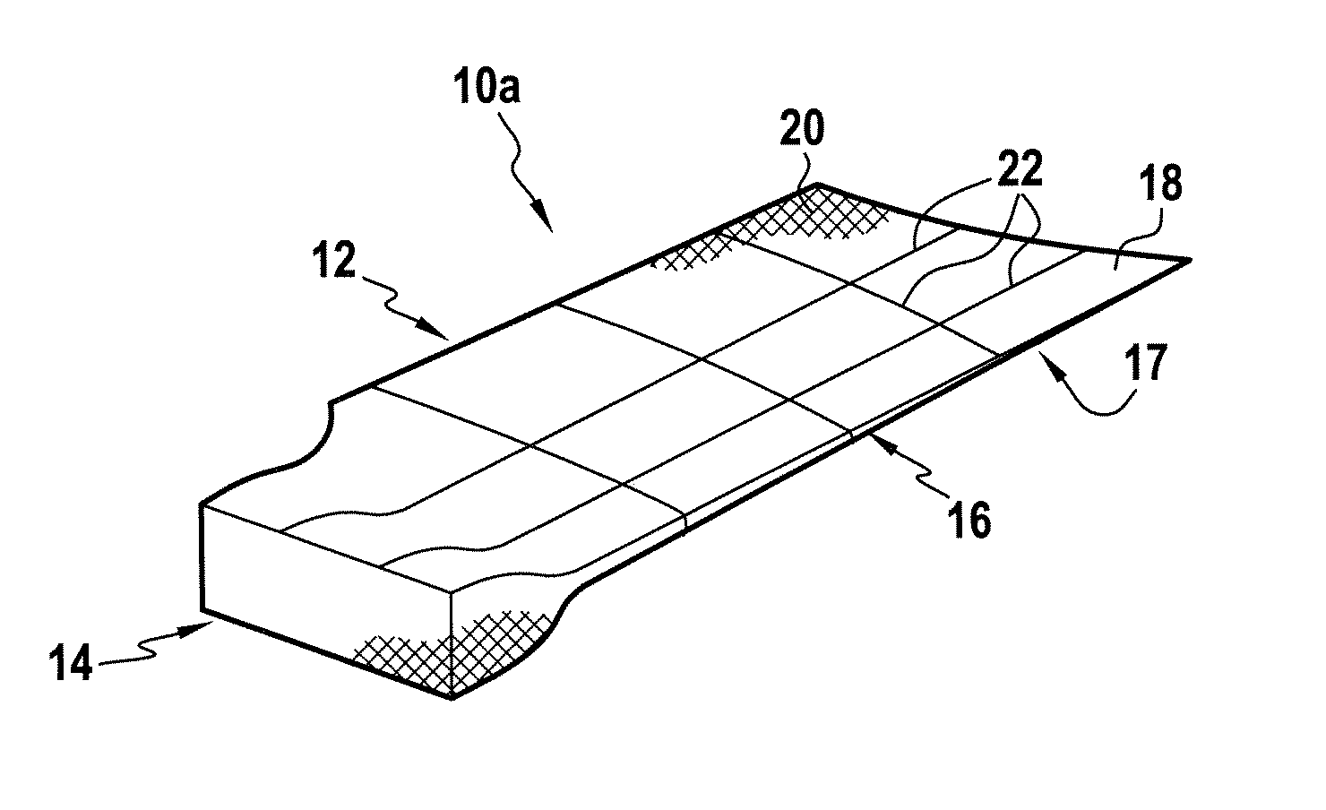
[0030]The method in accordance with the present invention is implemented starting with a preform of the kind that results from three-dimensional weaving, e.g. implemented in accordance with French patent document FR 2 861 143. Thus, the first step a) of the method consists in making such a three-dimensional preform by weaving, the preform comprising warp yarns and weft yarns. Amongst these two groups of yarns, tracer yarns are provided that can be identified visually amongst the others and that are situated regularly, at least at the surface of the preform.

[0031]Advantageously, said preform is made up of warp yarns and of weft yarns, with the direction of the warp yarns forming the longitudinal direction of the preform, said preform having at least a first portion made using a first weave for forming the airfoil of a blade, and a second portion, made using a second weave, for forming the root of the blade, with the first and second portions being united by a transition zone in which...


PUM

PropertyMeasurementUnit
temperatureaaaaaaaaaa
temperaturesaaaaaaaaaa

Abstract

The invention relates to a method of manufacturing a composite turbomachine blade, the method comprising the following steps:a) making a preform by three-dimensionally weaving yarns including tracer yarns disposed at least at the surface of the preform;b) cutting out said preform so as to leave intact a series of tracer yarns situated along a reference face of the preform;c) pre-deforming said cut-out preform;d) compacting and stiffening said pre-deformed preform;e) providing an injection mold in which said stiffened preform is placed;f) heating said injection mold;g) injecting a binder into said injection mold, the binder comprising a thermosettable resin; andh) extracting from the mold a composite molded part presenting substantially the shape and the dimensions of said blade.The invention is applicable to a making fan blade.

Description

[0001]The invention relates to a method of fabricating a composite turbomachine blade and to a blade obtained by the method.FIELD OF THE INVENTION[0002]The blade is a composite blade of the type comprising a preform of three-dimensionally woven fibers or yarns together with a binder maintaining the relative disposition between the yarns of the preform, said preform being made up of warp yarns and of weft yarns, the direction of the warp yarns forming the longitudinal direction of the preform.[0003]In particular, the present invention relates to a fan blade for a turbomachine, in particular a turbojet. Nevertheless, within the context of the present invention it is also possible to envisage making a blade for a low-pressure compressor in which the temperatures reached in operation are compatible with the thermomechanical strength of a blade of this type.BACKGROUND OF THE INVENTION[0004]Usually, composite material fan blades, in particular fan blades made of carbon fibers, are made fr...

Claims


Application Information

Patent Timeline
Patent Type & Authority Patents(United States)
IPC IPC(8): F01D5/14
CPCB29B11/16B29C70/24B29C70/48B29C70/543B29L2031/08B29C70/545B29C70/541F04D29/324F05D2240/303B29C70/461
Inventor COUPE, DOMINIQUEDAMBRINE, BRUNO JACQUES GERARDLEVEQUE, STEPHANE ANDREMAHIEU, JEAN-NOEL
Owner SN DETUDE & DE CONSTR DE MOTEURS DAVIATION S N E C M A
Why Eureka
Try Eureka