Check patentability & draft patents in minutes with Patsnap Eureka AI!

Image processing apparatus

Inactive Publication Date: 2009-09-01
SONY CORP
View PDF15 Cites 0 Cited by
  • Summary
  • Abstract
  • Description
  • Claims
  • Application Information

AI Technical Summary

Benefits of technology

[0022]An object of the present invention is to provide an image processing apparatus capable of performing flexible and high speed processing, wherein a memory region which is emptied due to a change of display resolution can be used as a texture memory, increase of overhead such as switching pages can be prevented, and a reduction of the performance is not caused.
[0029]According to the present invention, by providing a DRAM or other memory circuit and a logic circuit together in one semiconductor chip and by storing display data and texture data required by at least one graphic element in a built-in memory circuit, the texture data can be stored in a portion other than a display region, so the built-in memory can be efficiently used.
[0030]Also, by giving identical functions in the memory circuit in parallel as a plurality of independent modules, the efficiency of parallel operations is improved. When the number of bits of the data is simply large, the efficiency of use of data is deteriorated and improvement of the performance is limited to cases of certain conditions, but to improve the average performance, bit lines can be efficiently used by providing a plurality of modules having certain degrees of functions.
[0031]Further efficient usage of the bit lines becomes possible by tinkering with the arrangement of the built-in memory circuit, that is, the address space occupied by the independent memory plus function modules.
[0032]When there are frequent accesses to relatively fixed display regions as in drawing graphics, by arranging the display elements at adjacent addresses to be different memory blocks from each other in the display address space, the probability increases of the modules being able to perform processing simultaneously and the drawing performance can be improved. Frequent accesses to a fixed display region, when drawing inside the closed region of a triangle etc., result in access to adjacent addresses because the internal display elements are adjacent to each other.
[0033]Further, in order to store more texture data, the texture data can be compressed by storing indexes of index colors and values of a color look-up table therefor inside the built-in memory circuit. As a result, the built-in memory circuit can be efficiently used.

Problems solved by technology

Note that, even after it became possible to provide the DRAM and a logic circuit together, to hold the texture data inside has been difficult due to both the limit of the DRAM capacity and the processing speed.
First, the frame buffer memory which is emptied due to a change of the display resolution cannot be used as a texture memory.
This becomes a big disadvantage when trying to perform all of the processing in the limited capacity of a built-in DRAM.
Second, when making the frame buffer memory and the texture memory physically identical, in simultaneous access to the frame buffer memory and the texture memory, the overhead of switching pages of the DRAM etc. becomes large, so the performance has to be sacrificed.
These disadvantages are not particularly limited to a graphic drawing apparatus of a built-in DRAM type and have been disadvantages in systems of an externally provided DRAM type as well, but have not been as serious as the built-in type where the capacity is strictly limited.

Method used


Image

  • Image processing apparatus
  • Image processing apparatus
  • Image processing apparatus

Examples


Embodiment Construction

[0051]Below, preferred embodiments will be described with reference to the accompanying drawings.

[0052]In the present embodiment, an explanation will be made of a three-dimensional computer graphic system for displaying a desired three-dimensional image of any three-dimensional object model at a high speed on a display such as a CRT (cathode ray tube)—which is often used in personal computers etc.

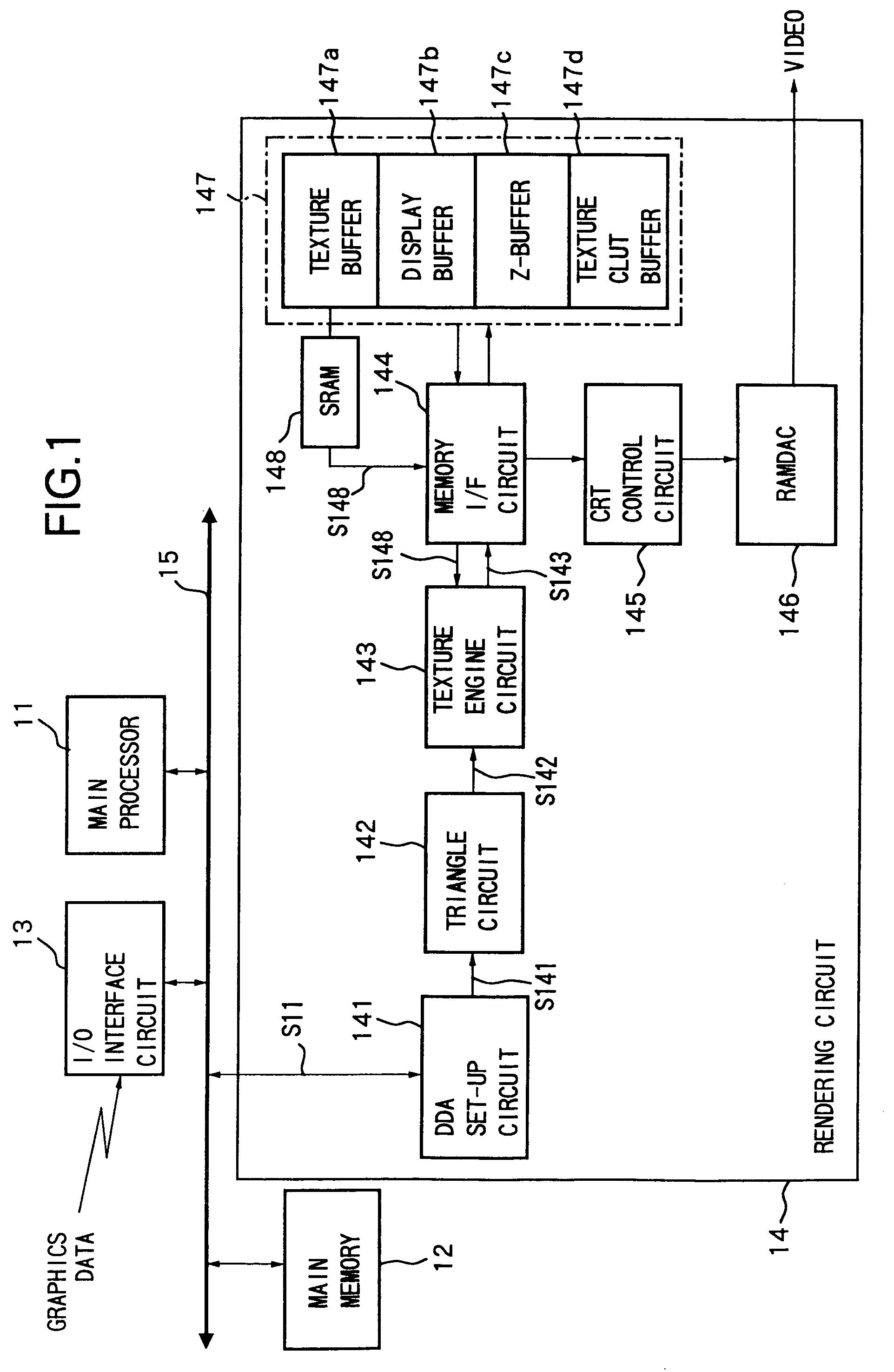
[0053]FIG. 1 is a view of the system configuration of a three-dimensional computer graphic system 10 as an image processing apparatus according to the present invention.

[0054]The three-dimensional computer graphic system 10 expresses a three-dimensional model as a composite of triangular unit graphics (polygons). By drawing the polygons, the colors of the pixels of the display screen are decided and the polygon rendering for display on the display is performed.

[0055]Also, in the three-dimensional computer graphic system 10, a three-dimensional object is expressed by using a z-coordinate ind...


PUM


Abstract

An image processing apparatus capable of performing flexible, high speed processing, wherein a memory region emptied due to a change of display resolution can be used as a texture memory, increase of an overhead such as switching pages can be prevented, and a decline in the performance is not caused. A built-in DRAM inside a semiconductor chip has a configuration for storing display data and the texture data required by at least one graphic element. The texture data can be stored in portions other than the display regions, so the built-in DRAM can be used efficiently and an image processing apparatus achieving both high speed operation and a reduction of power consumption can be realized.

Description

[0001]The present application is a continuation of the patent application Ser. No. 09 / 260,031 filed Mar. 2, 1999 now U.S. Pat. No. 6,803,918.BACKGROUND OF THE INVENTION[0002]1. Field of the Invention[0003]The present invention relates to a graphic drawing image processing apparatus, and more particularly to a technical field of storing texture data to be applied to a graphic element to be drawn in a built-in memory when a DRAM or other memory and a logic circuit are provided together.[0004]2. Description of the Related Art[0005]Computer graphics are often used in a variety of computer aided design (CAD) systems and amusement machines. Especially, along with the recent advances in image processing techniques, systems using three-dimensional computer graphics are becoming rapidly widespread.[0006]In three-dimensional computer graphics, the color value of each pixel is calculated at the time of deciding the color of each corresponding pixel. Then, rendering is performed for writing the...

Claims


Application Information

Patent Timeline
IPC IPC(8): G06F12/00G06T15/00
CPCG06T15/005
Inventor OHMORI, MUTSUHIROHORIOKA, TOSHIO
Owner SONY CORP
Features
  • R&D
  • Intellectual Property
  • Life Sciences
  • Materials
  • Tech Scout
  • Unparalleled Data Quality
  • Higher Quality Content
  • 60% Fewer Hallucinations
Learn More