Direct-current converter

a converter and direct current technology, applied in the direction of electric variable regulation, process and machine control, instruments, etc., can solve the problems of reducing the output voltage of the converter, affecting the efficiency of the d.c. converter, and the disadvantage of the large d.c. converter, so as to achieve the effect of reducing the output voltag

Inactive Publication Date: 2009-09-01
SANKEN ELECTRIC CO LTD
View PDF5 Cites 6 Cited by
  • Summary
  • Abstract
  • Description
  • Claims
  • Application Information

AI Technical Summary

Benefits of technology

[0025]Under the above-mentioned situation, an object of the present invention is to provide a direct-current converter which includes two switching elements whose reference potentials (source potentials) are in common with each other to simplify a driving circuit and which is compact and inexpensive with high efficiency in spite of small input voltage.

Problems solved by technology

In the converter of FIG. 1, additionally, its driving circuit is complicated due to the structure where respective source potentials (voltages) for the switching elements Q1, Q2 are different from each other.
Therefore, if the input voltage is small, losses at the reactor Lr and the current resonant capacitor Ci grow larger to cause a deterioration in the efficiency of the D.C. converter.
Alternatively, components for the reactor Lr and the current resonant condenser Ci become larger to cause the D.C. converter to be large-sized disadvantageously.

Method used


Image

  • Direct-current converter
  • Direct-current converter
  • Direct-current converter

Examples


first embodiment

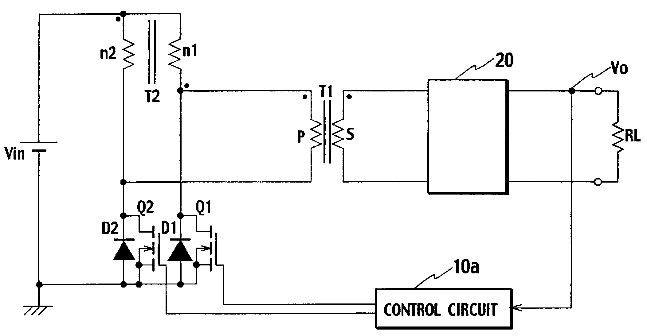
[0040]The operation of the D.C. converter of the first embodiment will be described below. Note that the principle of picking up the output voltage Vo from the transformer T1 is similar to that of the conventional D.C. converter described with reference to FIGS. 1 and 2. Thus, we are concerned here only with the reason why four times as much voltage as the voltage Vin of the D.C. power source is generated between both ends of the primary winding P of the transformer T1.

[0041]In the high-frequency converter circuit of FIG. 3 (including the transformer T2, the switching element Q1 and the switching element Q2), the switching element Q1 and the switching element Q2 repeat their ON / OFF states alternately to each other while interposing a “dead-time” period when these elements Q1, Q2 are turned OFF together.

[0042]When the switching element Q1 is turned ON while the switching element Q2 is turned OFF, the transformer T1 is provided, at one end (●: on the winding-start side) of the primary...

second embodiment

[0047]FIG. 4 is a circuitry diagram showing a direct-current (D.C.) converter in accordance with the present invention. This D.C. converter differs from the above-mentioned D.C. converter in that a series resonant circuit composed of the primary winding P of the transformer T1 and a capacitor C1 is interposed between one connection point between the first winding n1 of the transformer T2 and the drain of the switching element Q1 and another connection point between the second winding n2 of the transformer T2 and the drain of the switching element Q2.

[0048]In spite of the above difference, the operation of the D.C. converter of the second embodiment is similar to that of the D.C. converter of the first embodiment, allowing the similar effect to be afforded.

embodiment

3rd. Embodiment

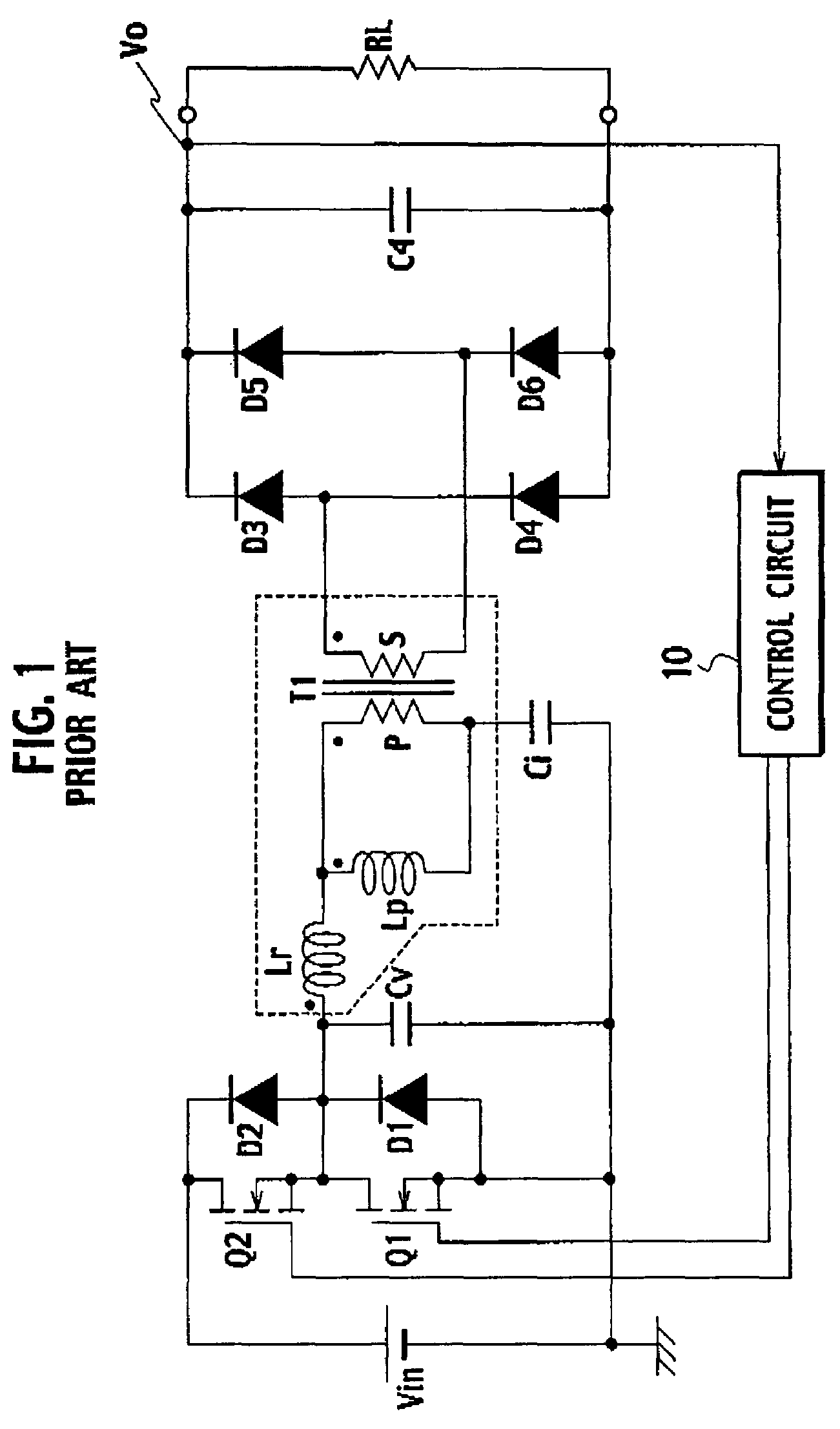
[0049]FIG. 5 is a circuitry diagram showing a direct-current (D.C.) converter in accordance with the third embodiment of the present invention. In the D.C. converter of the third embodiment, a voltage resonant capacitor Cv is connected in parallel with the connection point between the first winding n1 of the transformer T2 and the drain of the switching element Q1 and the connection point between the second winding n2 of the transformer T2 and the drain of the switching element Q2. Further, the D.C. converter includes a series resonant circuit where the primary winding P of the transformer T1, a current resonant capacitor Ci and a reactor Lr are connected with each other, in series. This series resonant circuit is connected in parallel with the former connection point and the latter connection point. The reactor Lr is formed by a leakage inductance between the primary side and the secondary side of the transformer T1. A reactor Lp is connected in parallel with the pri...


PUM


Abstract

A direct-current converter includes a high-frequency converting circuit converting voltage of a direct-current power source to alternating-current voltage, a transformer having primary and secondary windings P, S and a rectification smoothing circuit rectifying and smoothing voltage induced in the secondary winding. This converting circuit includes other transformer having first and second windings n1, n2, switching element Q1 having a source connected to a negative pole of the power source and a drain connected to a positive pole thereof through winding n1, and switching element Q2 having a source connected to the negative pole of the power source and a drain connected to the positive pole thereof through winding n2, element Q2 being turned on / off alternately to element Q1 being turned on / off. Winding P is connected to a point between winding n1 and the drain of element Q1 and another point between winding n2 and the drain of element Q2.

Description

BACKGROUND OF THE INVENTION[0001]1. Field of the Invention[0002]The present invention relates to a direct-current (D.C.) converter that is compact and inexpensive with high efficiency.[0003]2. Description of Related Art[0004]FIG. 1 shows a circuit diagram of a direct-current (D.C.) converter disclosed in Japanese Patent Publication Laid-open No. 2003-319650. In FIG. 1, this D.C. converter is formed by a half-bridge circuit. A series circuit consisting of a switching element Q1 (MOSFET) and a switching element Q2 (MOSFET) is connected to both ends of a direct-current (D.C.) power source Vin. In the switching element Q2, its drain is connected to a positive pole of the D.C. power source Vin. In the switching element Q1, its source of is connected to a negative pole of the D.C. power source Vin.[0005]Between the source of the switching element Q1 and its drain, a diode D1 and a voltage resonant capacitor Cv are connected in parallel with the switching element Q1, respectively. Further,...

Claims


Application Information

Patent Timeline
Patent Type & Authority Patents(United States)
IPC IPC(8): H02M3/335
CPCH02M3/3376Y02B70/1491H02M2001/0058H02M1/0058Y02B70/10
Inventor ASO, SHINJI
Owner SANKEN ELECTRIC CO LTD
Why Eureka
Try Eureka