Laser etched fiducials in roll-roll display

a technology of laser etching and roll-roll display, which is applied in the field of laser etching fiducials in roll-roll display, can solve the problems of inability to completely avoid, difficult detection, and complex lcds, so as to reduce the complexity of laser etching equipment, reduce the cost, time, inventory and waste, and increase the manufacturing yield

a technology of laser etching and roll-roll display, which is applied in the field of laser etching fiducials in roll-roll display, can solve the problems of inability to completely avoid, difficult detection, and complex lcds, so as to reduce the complexity of laser etching equipment, reduce the cost, time, inventory and waste, and increase the manufacturing yield

US7583834B2Active Publication Date: 2009-09-01EASTMAN KODAK CO

Image

  • Laser etched fiducials in roll-roll display
  • Laser etched fiducials in roll-roll display
  • Laser etched fiducials in roll-roll display

Examples


example 1

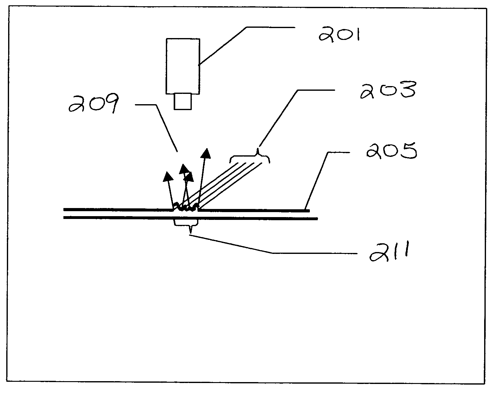
[0137]The error associated with pre-printing an alignment feature and then aligning the etching process to the feature versus creating the alignment feature during the etching process has been shown to be in the order of 0.001 inches, three sigma in both the x and y direction for a high precision machine using cameras, blob analysis and a Cartesian alignment mechanism. For less sophisticated equipment, the alignment error could be of a much larger magnitude. Even with precise equipment, alignment errors complicate the manufacture of segmented and pixilated displays and will increase waste and limit the ability to create small features in the case of segmented displays and in the case of pixilated displays making interconnection to high dpi displays more difficult.

[0138]The experiments were intended to estimate the precision with which a laser etched fiducial could be found. For that work, we evaluated the performance on both ITO putter-coated and uncoated PET support, also referred ...


PUM


Abstract

The present invention relates to a method of aligning comprising providing a support, applying a transparent layer, patterning at least the transparent layer to produce a pattern and an alignment feature capable of scattering light, illuminating the support and the transparent layer with oblique lighting, providing an analysis system capable of sensing scattered light from the alignment feature and referencing, sensing the scattered light from the alignment feature; referencing the scattered light from the alignment feature to a position on said support; and aligning a second operation to the position.

Description

FIELD OF THE INVENTION[0001]The present invention relates to a method for providing a particular alignment feature on a component layer of a multilayer product.BACKGROUND OF THE INVENTION[0002]In the manufacture of electronic devices, such as liquid crystal displays, where multiple layers of patterned materials are combined to form the display, precise registration of the layers is critical for proper function and acceptable performance.[0003]A liquid crystal display (LCD) is a type of flat panel display used in various electronic devices. At a minimum, an LCD comprises a support, such as glass or plastic, at least one conductive layer and a liquid crystal layer. LCDs may also be more complex and have additional components. For example, an LCD may comprise a transparent, multilayer flexible support, coated with a first patterned conductive layer and coated with a light-modulating liquid crystal layer. A second conductive layer is applied and overcoated with a dielectric layer to whi...

Claims


Application Information

Patent Timeline
01 Sep 2009
Publication
US7583834B2
IPC
G06K9/00
CPC
G03F7/70791; G03F9/7088; G03F9/7076
Inventors
MCCOLLOUGH, GEORGE T.; RZADCA, MARK C.