Controlling optical resonances via optically induced potentials

a technology of optical resonance and potential, applied in the field of self-adaptive, coupled strong confidence photonic devices, can solve the problems of extreme sensitivity of hic photonic circuits to fabrication uncertainties, number of challenges to be addressed, and the sensitivities of hic circuits

Inactive Publication Date: 2009-09-01
MASSACHUSETTS INST OF TECH
View PDF32 Cites 28 Cited by
  • Summary
  • Abstract
  • Description
  • Claims
  • Application Information

AI Technical Summary

Benefits of technology

[0010]Embodiments of the present invention include optomechanically variable photonic systems that utilize optical resonances to generate optically induced force and potential profiles. The optomechanical systems may include one or more optical resonators that passively track the frequency of an incident optical driving signal through the action of optical forces produced by the optical driving signal. In some embodiments, precise mechanical actuation of the mechanical state of the optomechanical system may be achieved through a change of the frequency of the optical driving signal. Further, the systems may enable the creation of highly localized and tailorable optically induced potential wells with which the mechanical state of the optomechanical system may be precisely controlled.

Problems solved by technology

However, numerous challenges need to be addressed to facilitate wide implementation of such integrated circuits.
Among these challenges are the extreme sensitivity of HIC photonic circuits to fabrication uncertainties, and the sensitivities of HIC circuits to the environment.
However, as optical cavities shrink to smaller and smaller dimensions, in the context of HIC integrated photonics, dimensional sensitivities of the cavity's resonance frequency make it difficult to directly fabricate a HIC cavity to the designed optical frequency.
In addition to their extreme sensitivities to dimensional variations, HIC photonic circuits, such as those made from silicon, tend to be sensitive to their environment.
For instance, since the refractive index of silicon changes rapidly with temperature, it may become challenging to stabilize the frequency of a cavity against thermal environmental variations.
Since a photonic microcavity, such as a microring, is generally of fixed dimensions, e.g., as a consequence of being “frozen” into a material on the surface of a lithographically patterned chip, tuning an integrated microcavity over a large wavelength range may be challenging.
For example, the device path-length typically may not be changed sufficiently to appreciably tune the resonant wavelength.
In this approach, the maximum tuning range is generally limited by the maximum thermal change that a heater can supply, or the maximum force that the material can sustain.

Method used


Image

  • Controlling optical resonances via optically induced potentials
  • Controlling optical resonances via optically induced potentials
  • Controlling optical resonances via optically induced potentials

Examples


Embodiment Construction

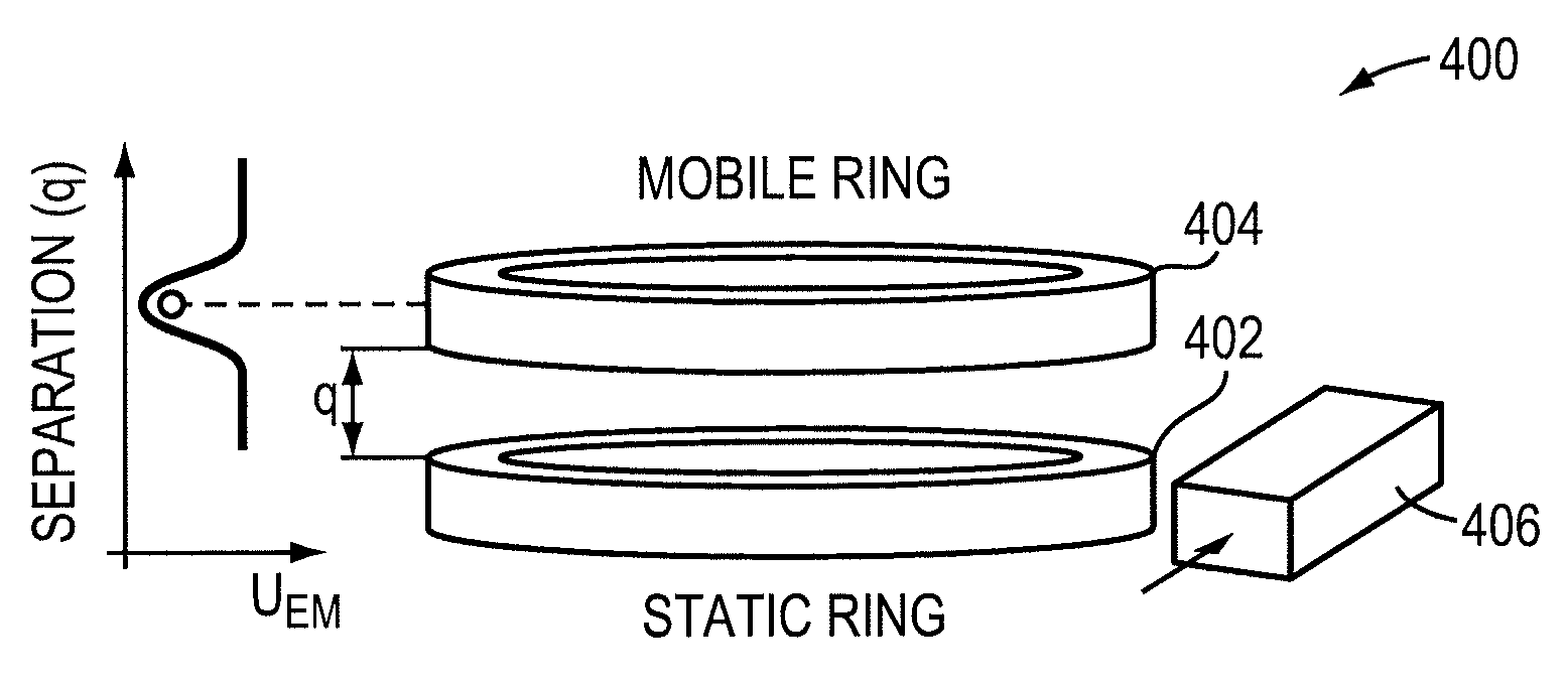
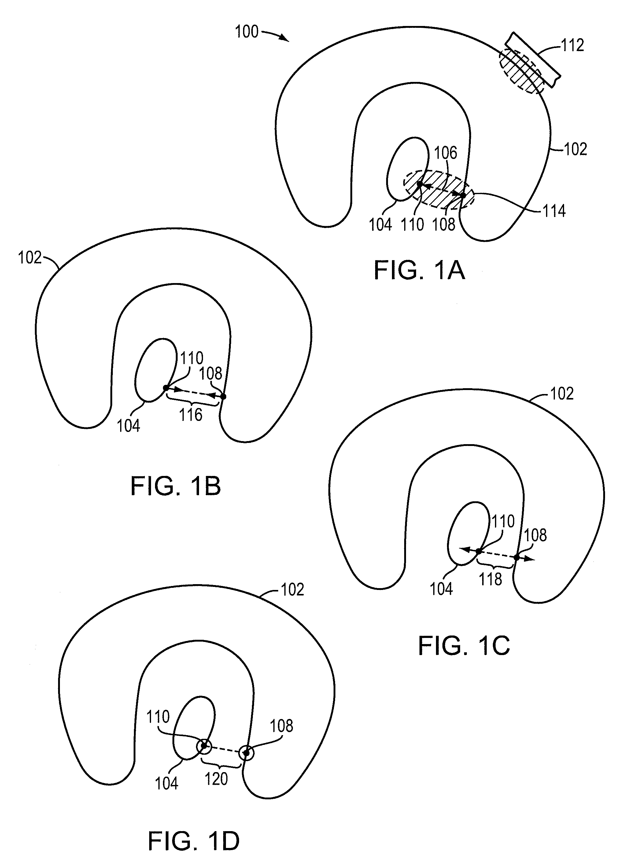
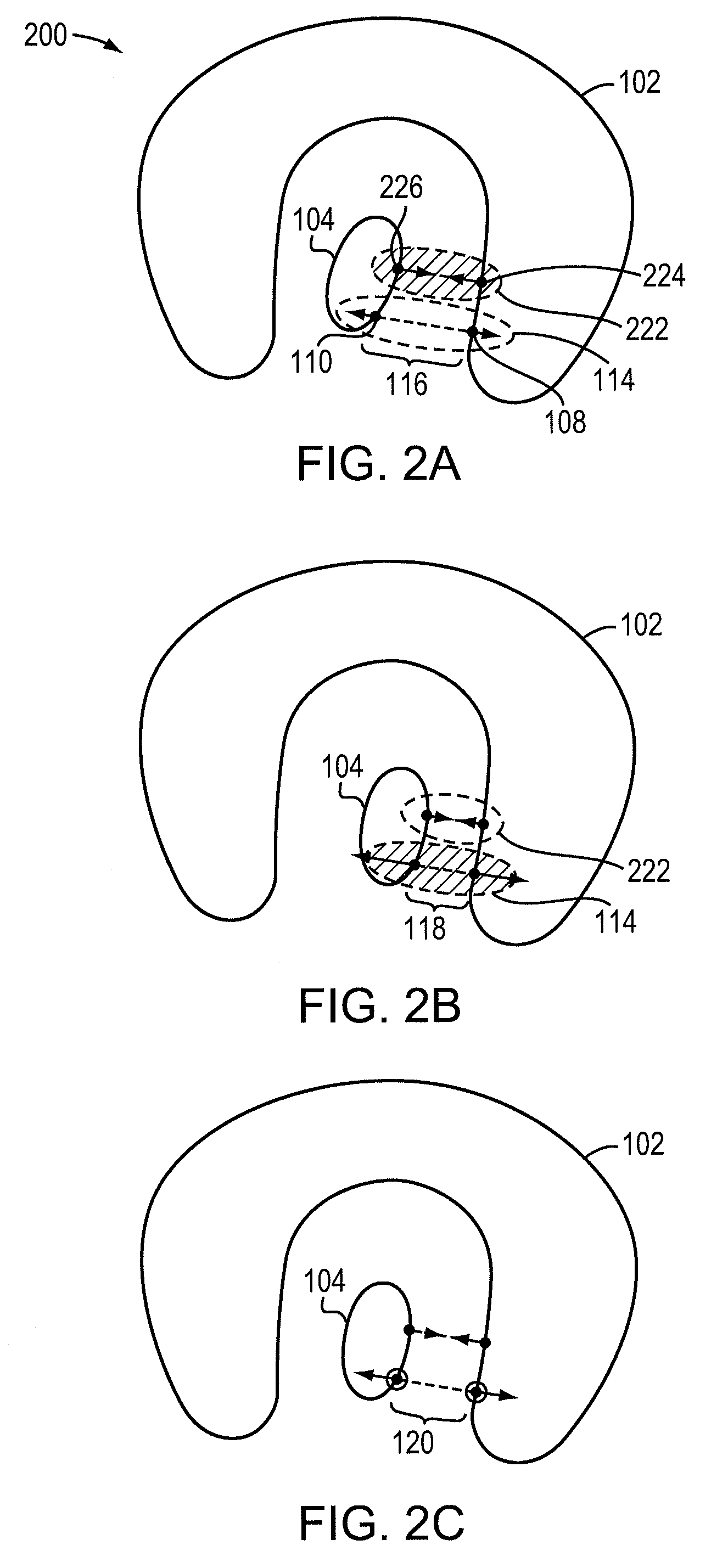
[0041]In general, embodiments of the invention use optical forces between optically coupled strong-confinement photonic devices to adjust a mechanical degree of freedom between the devices, such as a relative position or orientation. The setting of the mechanical degree of freedom, in turn, affects the strength of optical coupling, and, consequently, of the forces between the devices. At optical resonances of the combined system, the coupling is typically particularly strong. Moreover, the resonance frequencies may depend on the coupling. By exploiting this dependence, optomechanical systems that self-adjust to trap optical resonances, and / or spectrally bond the resonances to an input light signal, may be designed.

[0042]The devices used in various embodiments of the invention contain strong-confinement photonic structures (SCPS). As used herein, an SCPS is a structure capable of confining, and optionally enhancing, an optical-regime electromagnetic field within a space on the scale ...


PUM


Abstract

Influence of distance between two coupled strong-confinement photonic devices on optically resonant condition thereof and / or on optical forces.

Description

RELATED APPLICATIONS[0001]This invention claims priority to and the benefit of U.S. Provisional Application Ser. No. 60 / 984,253, filed Oct. 31, 2007, the entire contents of which are hereby incorporated by reference.GOVERNMENT LICENSE RIGHTS[0002]This invention was made with government support under Contract Number DAAD-19-02-D0002 awarded by Army Research Office through the Institute for Soldier Nanotechnologies. The government has certain rights in the invention.FIELD OF THE INVENTION[0003]The present invention generally relates to optomechanical devices for integrated optics, and, more particularly, to self-adaptive, coupled strong-confinement photonic devices.BACKGROUND[0004]The field of integrated photonics seeks to miniaturize optical components such as modulators, resonators, filters and waveguides, integrating them on a chip in the form of optical circuits. The fabrication of integrated photonic circuits through lithographic and other manufacturing methods promises to: (1) r...

Claims


Application Information

Patent Timeline
Patent Type & Authority Patents(United States)
IPC IPC(8): G02B6/42H01S3/00
CPCB82Y20/00G02B6/1223G02B6/12007
Inventor RAKICH, PETERPOPOVIC, MILOS
Owner MASSACHUSETTS INST OF TECH
Why Eureka
Try Eureka