Brush, commutator, and commutator device

a commutator and brush technology, applied in the direction of current collectors, dynamo-electric machines, electrical apparatus, etc., can solve the problems of difficult to further improve the rectification (rectification characteristic) and durability of the brush and the commutator, and the contact surfaces between the brushes and the commutator segments are likely to be electrically abraded. , the effect of reducing the amount of electric current passing between the brush and the high-resistive layer o

Inactive Publication Date: 2009-09-08
DENSO CORP +1
View PDF17 Cites 7 Cited by
  • Summary
  • Abstract
  • Description
  • Claims
  • Application Information

AI Technical Summary

Benefits of technology

[0008]The present invention is made in view of the foregoing matters, and it is an object of the present invention to provide a brush, a commutator and a commutator device, with enhanced rectification and durability.

Problems solved by technology

Therefore, contact surfaces between the brushes and commutator segments are likely to be electrically abraded by the intermittent conduction, in addition to mechanical abrasion by press-contacting.
This electric abrasion results from a discharge phenomenon (sparks) which occurs while the brushes repeatedly contact with and separate from the commutator segments.
Therefore, it is difficult to further improve rectification (rectifying characteristic) and durability of the brush and the commutator.
Therefore, it is difficult to further improve rectification and durability.

Method used


Image

  • Brush, commutator, and commutator device
  • Brush, commutator, and commutator device
  • Brush, commutator, and commutator device

Examples


first embodiment

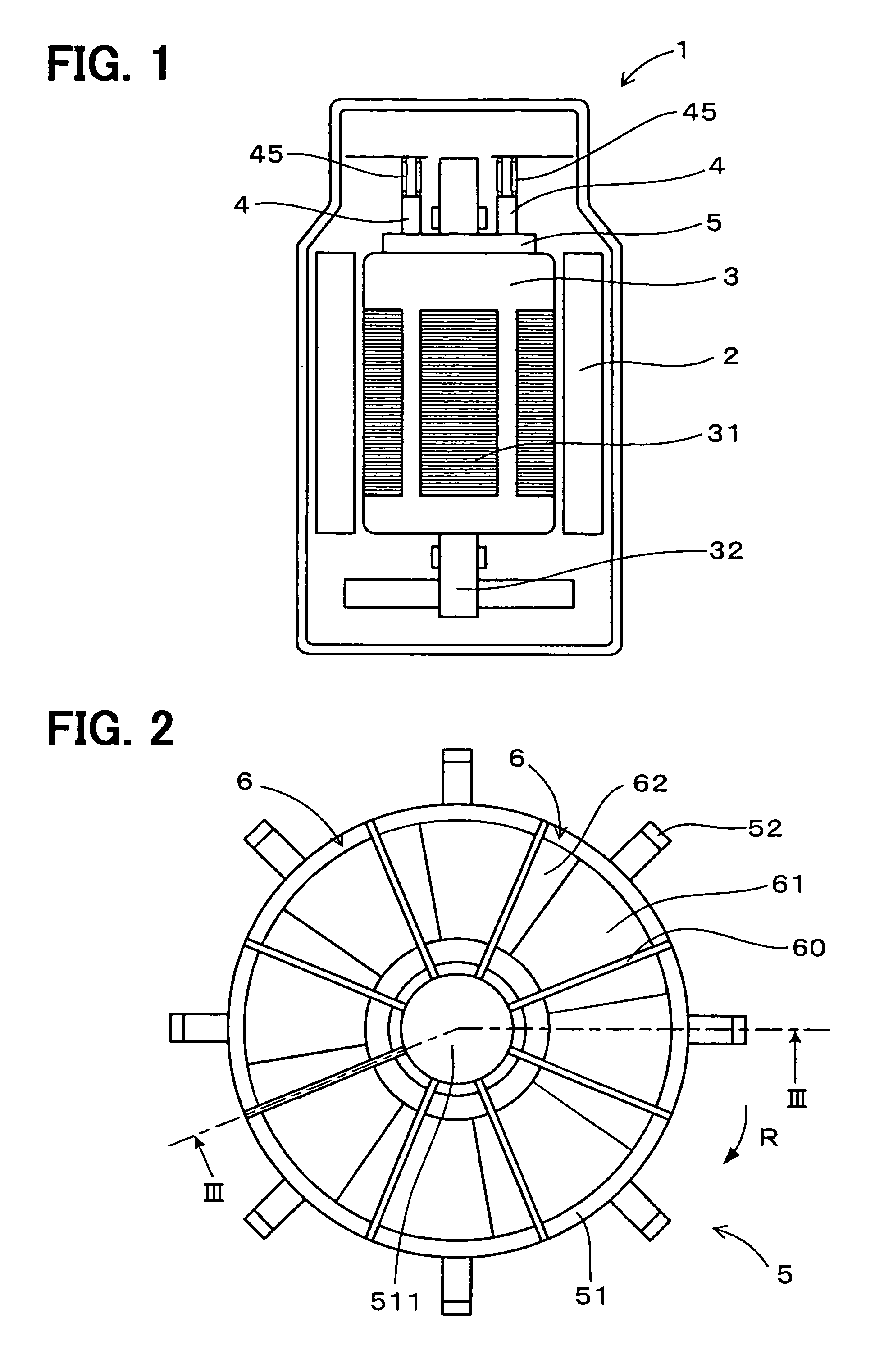
[0034]Referring to FIGS. 1 and 2, a brush 4 and a commutator 5 of the first embodiment are used in a d.c. motor 1 as a rotary electric machine. The d.c. motor 1 has a stator 2 provided with permanent magnets or a field winding, and a rotor 3 provided with a plurality of armature windings 31. A pair of brushes 4 is arranged on the stator 2 for supplying direct current. The commutator 5 is connected to a rotor shaft 32 of the rotor 3. The commutator 5 has a plurality of commutator segments 6 that are connected to the armature windings 31, respectively, as shown in FIGS. 4 and 5.

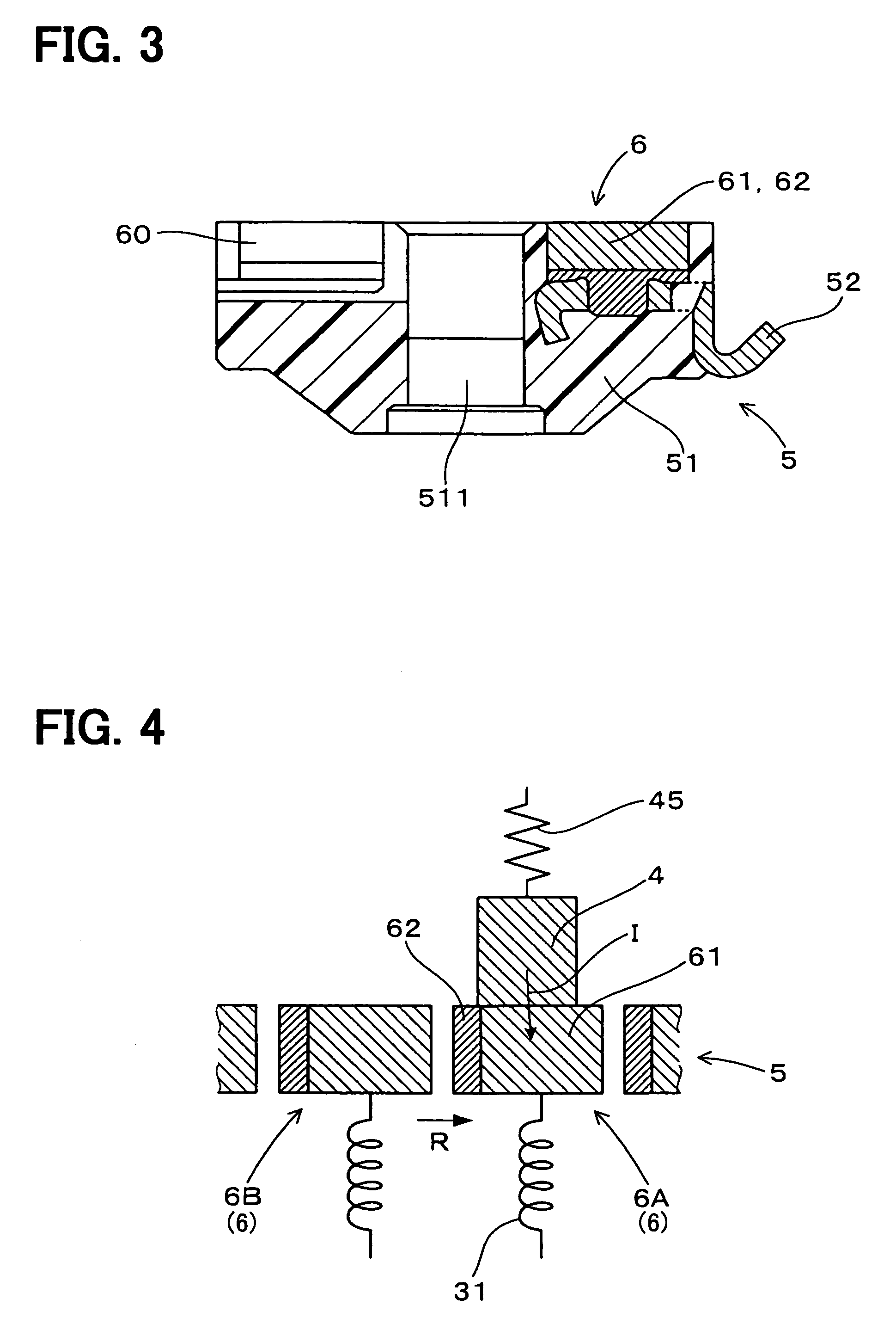
[0035]As shown in FIGS. 2 and 3, the commutator 5 is a flat-type, and is located on an axial end surface of the rotor 3 to make contact with the brushes 4. Specifically, the commutator segments 6 are mounted on a resinous body member 51 having a disk shape. The commutator segments 6 are arranged to extend from a center 511 of the body member 51 in a radial direction. Further, clearances 60 are defined between t...

second embodiment

[0053]Referring to FIGS. 6 and 7, a d.c. motor 1 of the second embodiment has the pair of brushes 4 each of which is constructed of two resistive layers and the commutator 5 having a plurality of commutator segments 6 each of which is constructed of a single layer. Specifically, each of the brushes 4 has a low-resistive layer 41 made of a low-resistive material and a high-resistive layer 42 made of a high-resistive material having a specific resistance higher than that of the low-resistive material.

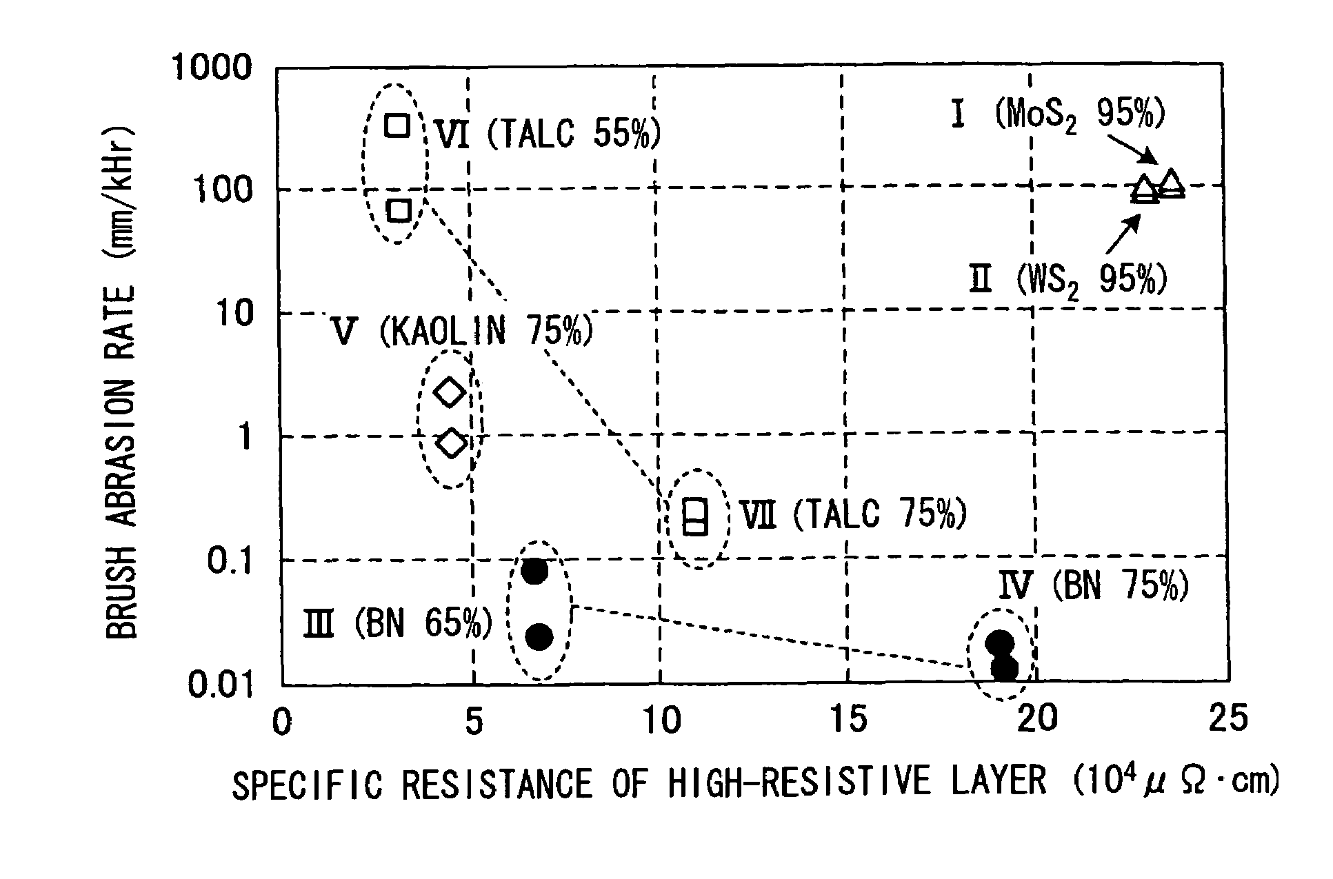
[0054]The low-resistive material contains a carbonic material and a binder. The high-resistive material contains a carbonic material, a binder, and boron nitride (BN) as an inorganic substance. Here, a mixing ratio of the boron nitride is higher than 20 wt % against a total weight of the high-resistive material.

[0055]The d.c. motor 1 of the second embodiment is used in a fuel pump for a vehicle, and a rotor 3 of the d.c. motor 1 is rotated in one direction R. As shown in FIGS. 6 and 7, ea...

third embodiment

[0067]Hereafter, an example of the method of producing the commutator 5 of the first embodiment and the brushes 4 of the second embodiment will be described.

[0068]The commutator segment 6 and the brushes 4 having two resistive layers 41, 42, 61, 62 are produced as follows.

[0069]First, as a method of producing the high-resistive material, carbonic powder such as graphite (e.g. 25 wt % natural graphite powder having an average particle diameter of 30 μm) and inorganic powder such as boron nitride (e.g. 75 wt % hexagonal boron nitride powder having an average particle diameter of 10 μm) are mixed into each other. Then, novolac phenol aldehyde resin (e.g. 15 weight ratio), which is dissolved in methanol solution (e.g. 30 weight ratio), is added in the mixed powder (100 weight ratio), as the binder. Further, the mixture is kneaded by a mixer, and to thereby produce the mixed material.

[0070]After, the mixed material is dried in a drier to evaporate methanol. Thus, a block of the high-resi...


PUM

PropertyMeasurementUnit
porosityaaaaaaaaaa
particle diameteraaaaaaaaaa

Abstract

In a commutator of a rotary electric machine, each of commutator segments has a low-resistive layer made of a low-resistive material and a high-resistive layer made of a high-resistive material having a specific resistance higher than that of the low-resistive material. The low-resistive material contains a carbonic material and a binder. The high-resistive material contains a carbonic material, a binder and an inorganic substance such as boron nitride. A mixing ratio of the inorganic material to the high-resistive material is more than 20 wt %. Alternatively, a brush, which makes contact with the commutator segments, can have the high-resistive layer and the low-resistive layer.

Description

CROSS REFERENCE TO RELATED APPLICATION[0001]This application is based on Japanese Patent Applications No. 2004-345982 filed on Nov. 30, 2004 and No. 2005-287714 filed on Sep. 30, 2005, the disclosures of which are incorporated herein by reference.FIELD OF THE INVENTION[0002]The present invention relates to a brush, a commutator, and a commutator device, which are used in a rotary electric machine such as an electric machine and a generator.BACKGROUND OF THE INVENTION[0003]In a generator such as a d.c. motor, generally, a pair of brushes is arranged on a stator and a commutator is arranged on a rotor. In the rotor, a plurality of armature windings are connected to commutator segments of the commutator, respectively. The pair of brushes is sequentially pressed against the commutator segments to supply the armature windings with electric currents, thereby rotating the rotor.[0004]However, the brushes and the commutator segments are intermittently and repeatedly in contact with each oth...

Claims


Application Information

Patent Timeline
Patent Type & Authority Patents(United States)
IPC IPC(8): H02K13/00
CPCH02K13/10H02K13/006H01R39/20H01R39/06
Inventor HAMAMATSU, HIROTAKEMURAKAMI, YOUICHIHONBO, RYOICHIKIYOSE, KENZOIKEDA, MITSUOSAKAURA, YOICHINAKAGAWA, SHINYANISHIO, MAKOTO
Owner DENSO CORP
Why Eureka
Try Eureka