Method for starting a continuous steam generator and continuous steam generator for carrying out said method

a technology of continuous steam and generator, which is applied in the direction of steam generation using steam absorption, steam generation using hot heat carriers, fire-box steam boilers, etc., can solve the problems of complicated cooling, low gas turbine emissions, waste heat from gas turbines that cannot be completely absorbed by the steam circuit of the steam turbine, etc., to achieve flexible and simple control, simple and technically uncomplicated, and reduce the effect of steam temperatur

Inactive Publication Date: 2009-09-08
SIEMENS AG
View PDF19 Cites 33 Cited by
  • Summary
  • Abstract
  • Description
  • Claims
  • Application Information

AI Technical Summary

Benefits of technology

[0012]The object on which the invention is based is therefore to specify a method for starting a continuous-flow steam generator of the abovementioned type, by means of which, using comparatively simple means, the temperature of the steam emerging from the tubes of the superheater heating surface can be reliably controlled and comparatively short startup times can be achieved. A continuous-flow steam generator of the abovementioned type which is particularly suitable for performing the method will also be specified.

Problems solved by technology

A short startup time of a gas turbine is desirable because it results in the starting losses occurring during the starting operation and consequently the emissions of the gas turbine being kept low.
For technical reasons, in particular due to the thermal inertia of its large masses, the steam turbine requires a longer startup time than the gas turbine and therefore predetermines the lower limit for the necessary startup times. Since the gas turbine therefore “leads” the steam turbine, the waste heat from the gas turbine cannot be absorbed completely by the steam circuit of the steam turbine during the startup operation of the gas and steam turbine plant.
This cooling is the more complicated, the further the gas turbine “leads” the steam turbine during startup.
However, the temperature of the steam when it emerges from the superheater can be controlled only within certain limits with the aid of injection cooling, with the result that even with measures of this type a certain warming-up time for the steam turbine still generally remains.
Moreover, the use of the separate cooling device is technically complex.

Method used


Image

  • Method for starting a continuous steam generator and continuous steam generator for carrying out said method
  • Method for starting a continuous steam generator and continuous steam generator for carrying out said method

Examples


Embodiment Construction

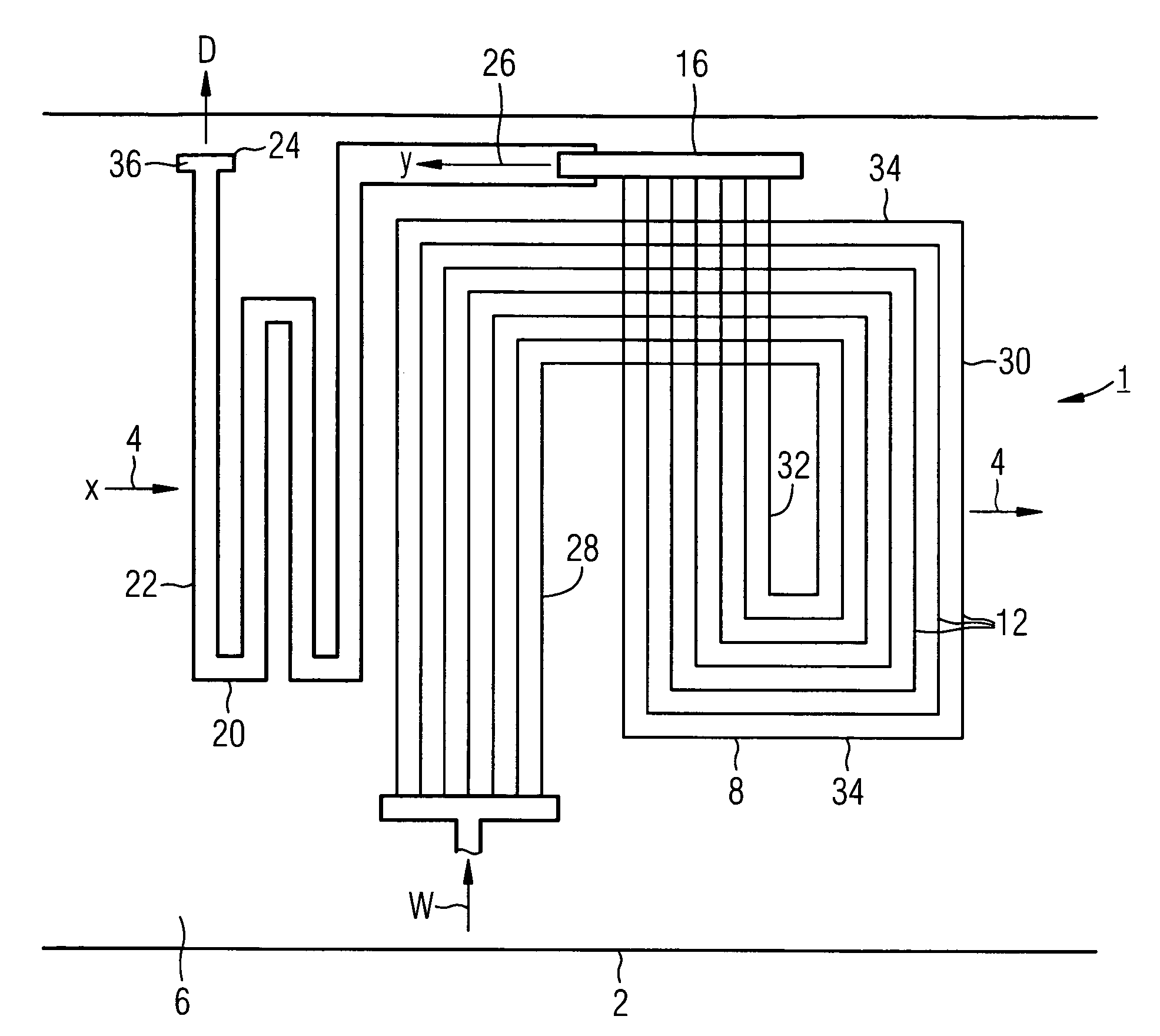
[0030]The continuous-flow steam generator 1 according to FIG. 1 is connected downstream of a gas turbine (not shown in any more detail) on the exhaust gas side in the manner of a waste-heat steam generator. The continuous-flow steam generator 1 has a containment wall 2 which forms a heating gas duct 6 through which the flow is capable of flowing in an approximately horizontal heating gas direction x, indicated by the arrows 4, for the exhaust gas from the gas turbine. A number of heating surfaces, configured on the continuous-flow principle, for the preheating, evaporation and superheating of the flow medium are arranged in each case in the heating gas duct 6. In the exemplary embodiment according to FIG. 1, only one evaporator continuous-flow heating surface 8 is shown for the evaporation section, but a larger number of continuous-flow heating surfaces may also be provided.

[0031]The evaporator system formed from the evaporator continuous-flow heating surface 8 can be acted upon by ...


PUM

PropertyMeasurementUnit
temperatureaaaaaaaaaa
feed rateaaaaaaaaaa
pressureaaaaaaaaaa

Abstract

The invention relates to a continuous steam generator provided with an evaporator through flow heating surface which is disposed in a heating gas channel which can be cross flown in an approximately vertical manner in a heating gas device, said evaporator through flow heating surface comprising a plurality of parallel connected steam generating pipes enabling a flow medium to flow through, and an overheating heating surface which is arranged downstream from the evaporator through flow heating surface comprising a plurality of parallel connected overheating pipes enabling the evaporated flow medium to flow through, also enabling production and operational costs to be reduced and enabling the temperature of the steam on the outlet of the overheating heating surface to be controlled in a comparatively simple and flexible manner. The steam end-point of the flow medium is displaced to the overheating pipe, if required. The continuous heating surfaces and the overheating heating surfaces are combined to form one functional unit such that the overheating heating surface can be used as a steam heating surface in a continuous steam generator which is particularly suitable for carrying out said method.

Description

CROSS REFERENCE TO RELATED APPLICATION[0001]This application is the US National Stage of International Application No. PCT / EP2004 / 008655, filed Aug. 02, 2004 and claims the benefit thereof. The International Application claims the benefits of European Patent application No. 03020020.8 EP filed Sep. 3, 2003, both of the applications are incorporated by reference herein in their entirety.FIELD OF THE INVENTION[0002]The invention relates to a continuous-flow steam generator of the horizontal type of construction, in which there are arranged, in a heating gas duct through which the flow can pass in an approximately horizontal heating gas direction, an evaporator continuous-flow heating surface, which comprises a number of steam generator tubes connected in parallel to allow a flow medium to flow through, and a superheater heating surface which is connected downstream of the evaporator continuous-flow heating surface and which comprises a number of superheater tubes connected in parallel...

Claims


Application Information

Patent Timeline
Patent Type & Authority Patents(United States)
IPC IPC(8): F22B1/20F22B13/12F22D1/00F22B1/18F22B29/06F22B35/14
CPCF22B1/1815F22B35/14F22B29/06Y02P80/10
Inventor FRANKE, JOACHIMKRAL, RUDOLFSCHIESSER, DIETER
Owner SIEMENS AG
Why Eureka
Try Eureka