Pipelined access by FFT and filter units in co-processor and system bus slave to memory blocks via switch coupling based on control register content

a coprocessor and filter unit technology, applied in the direction of computation using denominational number representation, sustainable buildings, instruments, etc., can solve the problems of significant system power consumption, battery life and thus system power consumption, and the inability to effectively use hearing aids in noisy environments such as restaurants and arenas, so as to reduce the number of memory accesses required for co-processor execution.

Active Publication Date: 2009-09-08
TEXAS INSTR INC
View PDF4 Cites 25 Cited by
  • Summary
  • Abstract
  • Description
  • Claims
  • Application Information

AI Technical Summary

Benefits of technology

[0010]It is therefore an object of this invention to provide a processing architecture and method of operating the same in which memory accesses required for co-processor execution are reduced.

Problems solved by technology

However, the implementation of a co-processor into a computing system complicates system operation, to some extent.
For example, a common problem faced by hearing aid wearers in the past was due to conventional hearing aids amplifying noise along with the desired speech or sound, making the hearing aid effectively useless in noisy environments such as restaurants and arenas.
Of course, battery life and thus system power consumption is a significant issue in portable computing systems.
Hearing aids are especially sensitive to battery life.
However, the passing of data to and from the co-processor, either via the CPU or by way of the co-processor directly accessing main memory, necessarily involves substantial power consumption.
The power consumption involved in these memory accesses, as repeatedly performed in digital signal processing routine such as a Discrete Fourier Transform or digital filter, can be significant, especially in miniature battery-powered systems such as hearing aids.

Method used


Image

  • Pipelined access by FFT and filter units in co-processor and system bus slave to memory blocks via switch coupling based on control register content
  • Pipelined access by FFT and filter units in co-processor and system bus slave to memory blocks via switch coupling based on control register content
  • Pipelined access by FFT and filter units in co-processor and system bus slave to memory blocks via switch coupling based on control register content

Examples


Embodiment Construction

[0024]The present invention will be described in connection with its preferred embodiment, namely as implemented into a system including a digital signal processor (DSP) as a co-processor, because it is contemplated that this invention will be especially beneficial when implemented into such a system. However, it is also contemplated that this invention will be useful and beneficial in a wide range of systems, system architectures, and system applications. Accordingly, it is to be understood that the following description is provided by way of example only, and is not intended to limit the true scope of this invention as claimed.

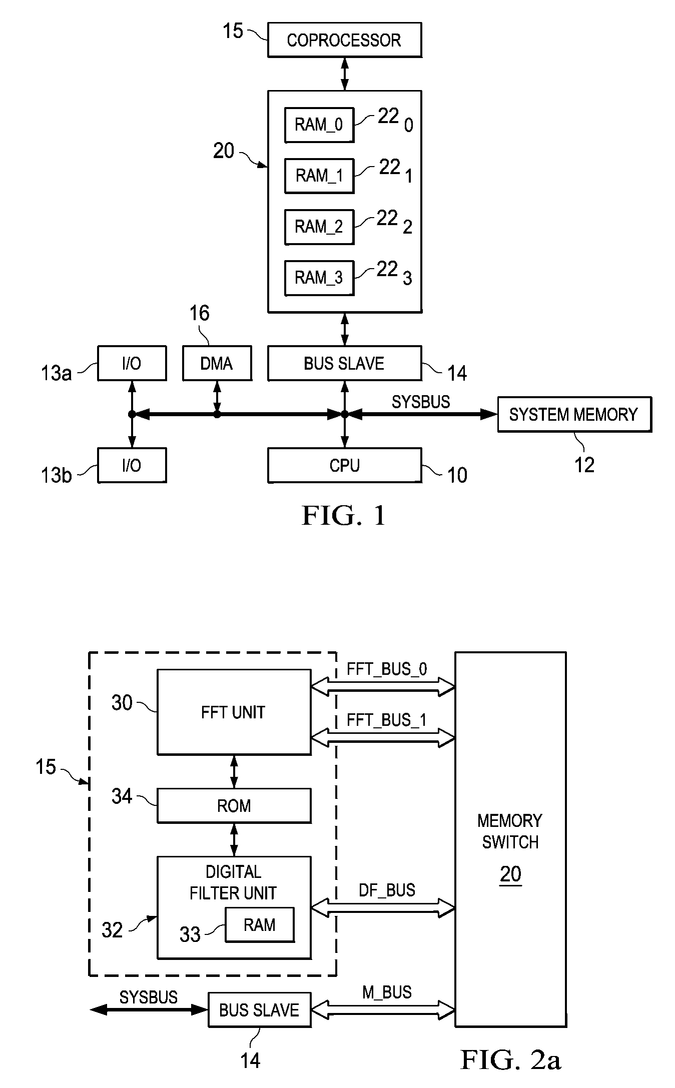
[0025]FIG. 1 illustrates, in the form of a block diagram, the construction of a computing or processing system constructed according to the preferred embodiment of the invention. The system of FIG. 1 includes central processing unit (CPU) 10, which includes and operates as the main system control unit, and the main arithmetic and logic unit (ALU) of the syst...


PUM


Abstract

A system architecture including a co-processor and a memory switch resource is disclosed. The memory switch includes multiple memory blocks and switch circuitry for selectably coupling processing units of the co-processor, and also a bus slave circuit coupled to a system bus of the system, to selected ones of the memory blocks. The memory switch may be constructed as an array of multiplexers, controlled by control logic of the memory switch in response to the contents of a control register. The various processing units of the co-processor are each able to directly access one of the memory blocks, as controlled by the switch circuitry. Following processing of a block of data by one of the processing units, the memory switch associates the memory blocks with other functional units, thus moving data from one functional unit to another without requiring reading and rewriting of the data.

Description

CROSS-REFERENCE TO RELATED APPLICATIONS[0001]This application claims priority, under 35 U.S.C. §119(e), of Provisional Application No. 60 / 736,436, filed Nov. 14, 2005, which is incorporated herein by this reference.STATEMENT REGARDING FEDERALLY SPONSORED RESEARCH OR DEVELOPMENT[0002]Not applicable.BACKGROUND OF THE INVENTION[0003]This invention is in the field of processing circuitry architecture, and is more specifically directed to memory management for co-processing architectures.[0004]As is fundamental in modern computer architectures, virtually all computer or processing architectures include input and output functions, a control function, arithmetic and logic functionality, and memory. And as is also fundamental in the art, efficient communication of information between the memory resources and the arithmetic and logic unit (ALU) is important in achieving high system performance. As such, many advances have been made in computing and processing architectures to improve this fu...

Claims


Application Information

Patent Timeline
Patent Type & Authority Patents(United States)
IPC IPC(8): G06F13/00
CPCG06F9/3879G06F15/7864Y02B60/1225Y02D10/00
Inventor ROYER, MARC E.SIRAVARA, BHARATH M.BARTLING, STEVEN C.BRANCH, CHARLES M.GALABERT, PEDRO R.MOGOTRA, NEERAJKAMATH, SAMIL D.
Owner TEXAS INSTR INC
Why Eureka
Try Eureka