Filtered electrical connector and combination having same

a technology of electrical connectors and filters, applied in the direction of charging stations, coupling device connections, transportation and packaging, etc., can solve the problems of radio frequency interference, interference with the electrical functions of the electrical center and conventional electrical devices, and unsatisfactory levels of electromagnetic interference (emi)

Active Publication Date: 2009-09-15
APTIV TECH LTD
View PDF14 Cites 16 Cited by
  • Summary
  • Abstract
  • Description
  • Claims
  • Application Information

AI Technical Summary

Benefits of technology

[0005]The present invention provides to a filtered electrical connector that can be installed in a pass-through hole in a housing to filter undesired frequencies of alternating current from an electrical circuit inside the housing at the pass-through hole. Filtering undesired frequencies of alternating current of the internal electrical circuit as it exits the housing result in a very effective filter.
[0008]The filtered electrical connector may comprises an alignment cap configured to provide alignment for cantilevered output grounding terminals as the filtered electrical connector is inserted into the pass-through hole and attached to the housing. The alignment cap may also be configured to provide over-stress protection for the cantilevered output grounding terminals and may also be configured to provide retention of a peripheral seal.
[0010]The filtered electrical connector may be configured to provide a chamber for the PCB assembly that accepts the dispensing and curing of sealant such as a silicone sealant around the male blade terminal and filtering devices, on at least one side of the PCB, thereby providing strain relief to the devices and enabling the filtered electrical connector to be sealed even in the absence of a mating female connector.

Problems solved by technology

It has been found that undesirable levels of electromagnetic interference (EMI) are coupled to this high current power circuit that is provided by the APM.
Conducting these undesirable levels of EMI outside the APM housing results in radio frequency interference as well as interference with the electrical functions of the electrical center and conventional electrical devices in the vehicle.
This known method is not only expensive but also does not meet the desired EMI compliance limit in many cases.

Method used


Image

  • Filtered electrical connector and combination having same
  • Filtered electrical connector and combination having same
  • Filtered electrical connector and combination having same

Examples


Embodiment Construction

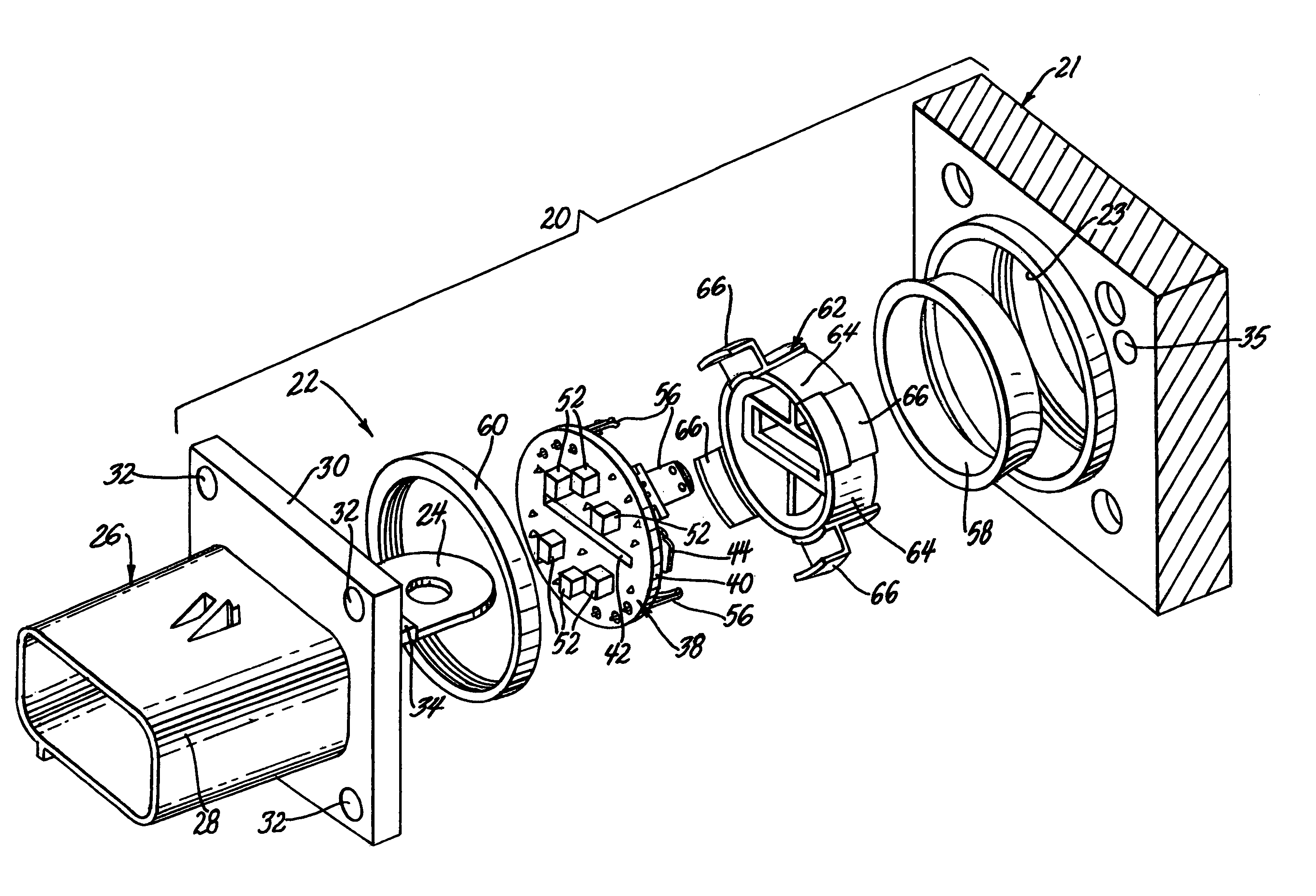
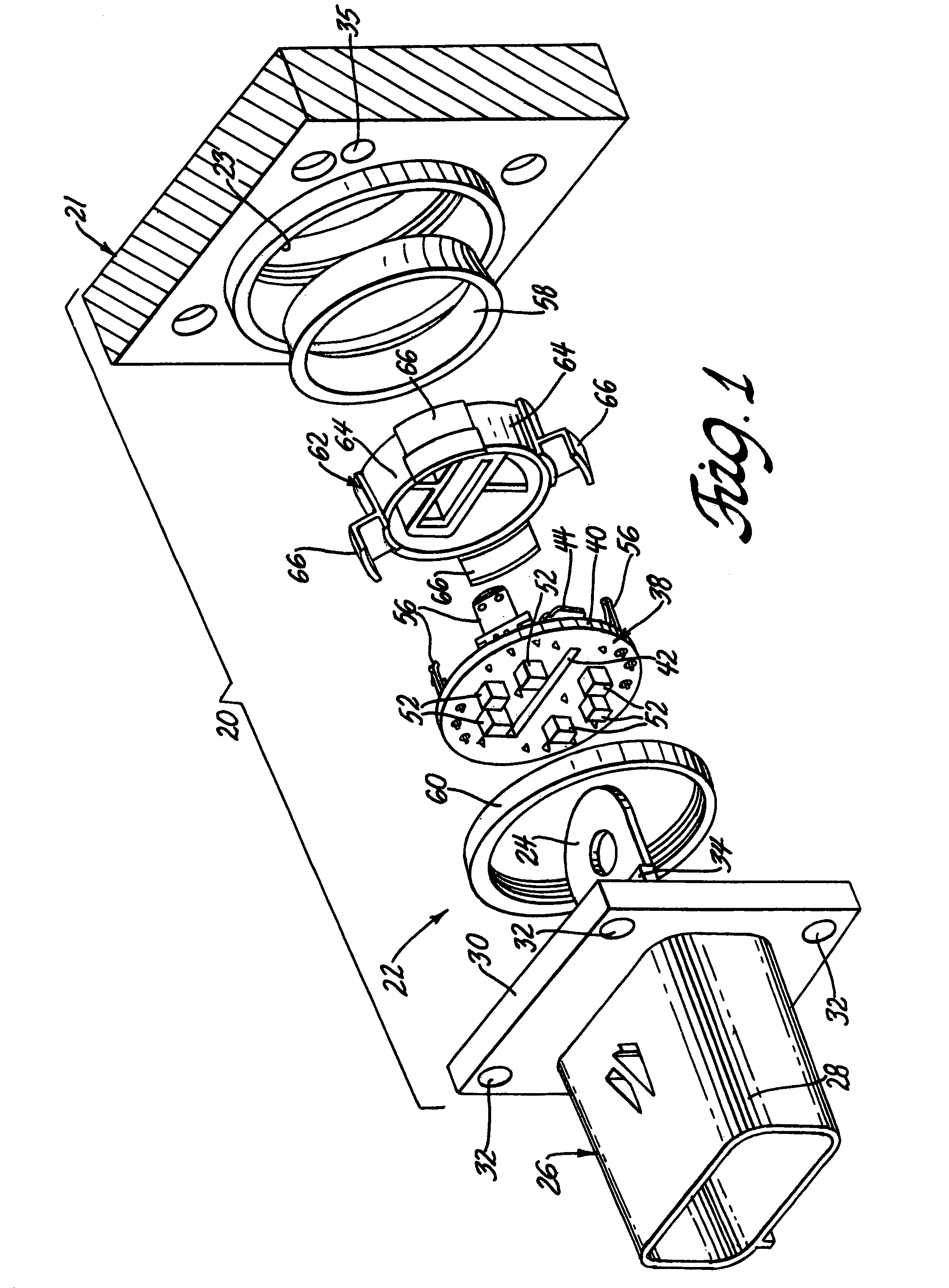
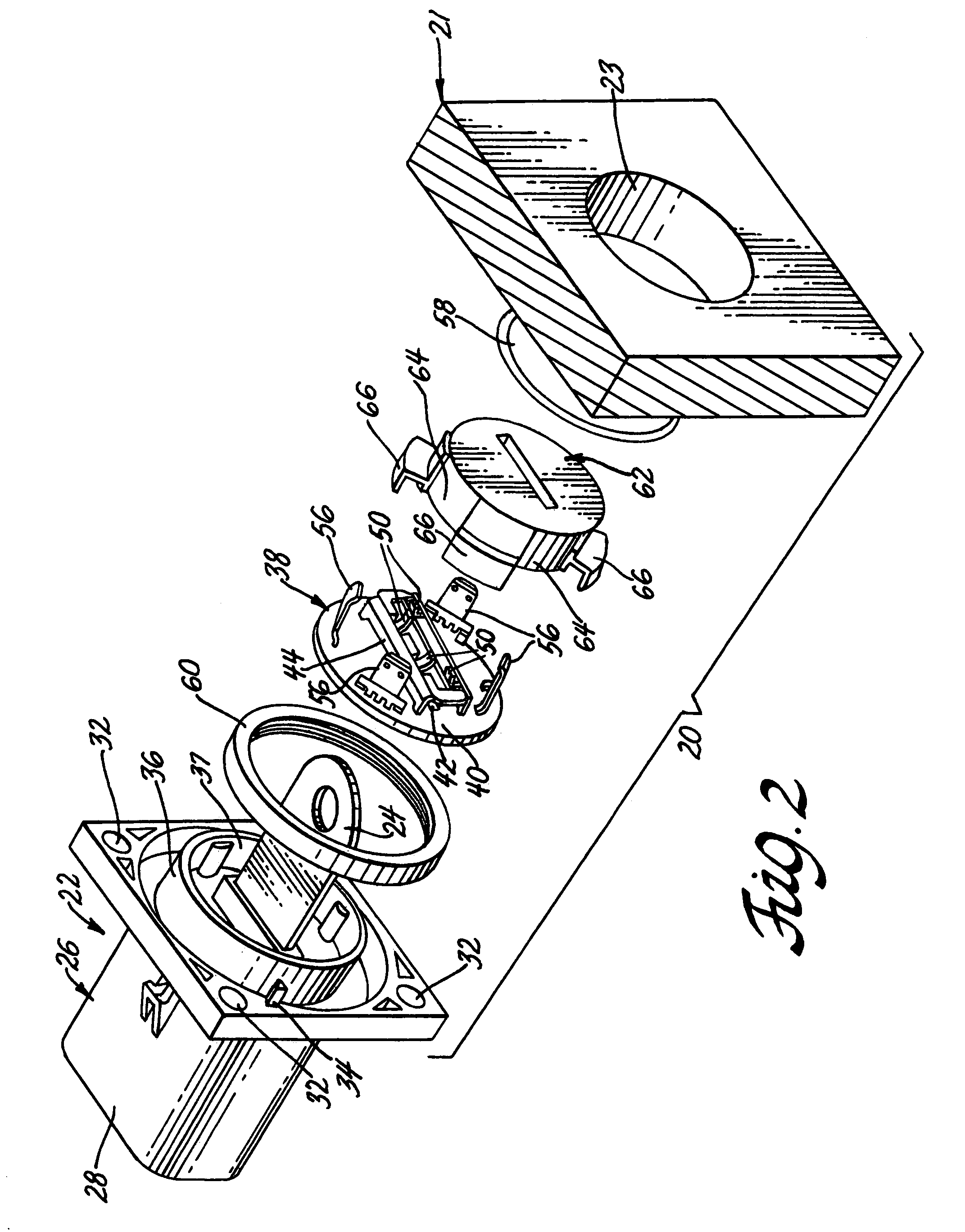
[0022]In reference to FIGS. 1-8, an auxiliary power module 20 comprises a metal housing 21, usually cast aluminum, and a filtered electrical connector 22 that is attached to the metal housing 21 at a pass-through hole 23. The filtered electrical connector 22 comprises a male blade terminal 24 that is preferably insert molded in a plastic connector body 26. A first end of the male blade terminal 24 accepts a suitable female terminal (not shown), while the second end accepts a bolted connection to a bus bar inside the metal housing 21 of auxiliary power module 20 as best shown in FIG. 4.

[0023]Connector body 26 may include a shroud or socket 28 at a rearward end that accepts a mating electrical connector plug (not shown) that houses the female terminal that connects to the first end of the male blade terminal 24. Connector body 26 has a medial rectangular flange 30 with corner holes 32 that accept a series of attachment screws 33 for attaching the plastic connector body 26 to the metal...


PUM


Abstract

A filtered electrical connector for a power module comprises a connector body having a back wall partly defining a chamber at one end of the connector body. An alternating current filter is retained in the chamber, and a terminal extends through the back wall, the chamber, and the alternating current filter disposed in the chamber. The filtered electrical connector is attached to a housing having a metal portion with the chamber disposed in a pass-through hole of the housing. The terminal is attached to an electrical circuit inside the housing and the alternating current filter is grounded on the metal portion of the housing to filter alternating current flowing outside of the housing from the electrical circuit inside the housing via the terminal.

Description

REFERENCE TO RELATED APPLICATIONS[0001]This application claims the benefit of U.S. Provisional Ser. No. 60 / 844,826 filed Sep. 15, 2006.BACKGROUND OF THE INVENTION[0002]The present invention relates generally to electrical connectors and more particularly to a filtered electrical connector and a combination having same.[0003]In hybrid vehicle electrical systems, an auxiliary power module (APM) provides a high current 14 volt power circuit for a conventional electrical center and other conventional electrical devices in the vehicle, such as those in lighting, entertainment and climate control systems. It has been found that undesirable levels of electromagnetic interference (EMI) are coupled to this high current power circuit that is provided by the APM. Conducting these undesirable levels of EMI outside the APM housing results in radio frequency interference as well as interference with the electrical functions of the electrical center and conventional electrical devices in the vehic...

Claims


Application Information

Patent Timeline
Patent Type & Authority Patents(United States)
IPC IPC(8): H01R13/66
CPCB60L11/1818H01R13/65802H01R13/719H01R13/6658B60L2270/147Y02T90/14H01R2201/26Y02T10/7005Y02T10/7072B60L53/16Y02T10/70
Inventor BLASKO, RAYMOND J.MESSURI, DOMINIC A.LUI, HOIBEER, ROBERT C.MARGRAVE, CHRISTOPHER A.
Owner APTIV TECH LTD
Why Eureka
Try Eureka